XIII. Join Lower Flange (Join_Upper_2_Base__TP_1_5_100N and Join_Upper_2_Base__Tie_2-4)
Purpose and usage:
•Applied only between flexible parts, deforming both parts, based on their stiffness.
•This is a permanent operation and can be applied to any attachment method such as welding, bolting, gluing, and riveting.
•Join has Type, Joining Force, Direction, and Sequence that can be set by the user.
o Type has three options:
§ Target Plane - applies the specified force on both parts, deforming the object and target part based on the stiffness (material properties) of each part. Both Object and Target points are then permanently fixed in relationship to each other (the object and target points are not necessarily on top of each other at the end of this operation).
§ Coincident - applies the specified force on both parts, deforming the object and target part until the object and target points are coincident, based on the stiffness of each part. Both Object and Target points are then permanently fixed in relationship to each other.
§ Tie - will maintain relationship between the paired points in all 6DOF without deforming the parts. Move points added to the Tie will not change their nominal position relative to each other whether there is an initial gap between them or not. Tie is the equivalent of a rigid element used in FEA software.
o Joining Force: A specific force value can be added, otherwise if Infinite is specified, the necessary force to bring the parts together at the joining location will be used. Sometimes the specified value is insufficient to completely bring the joined points together. In this case the move will not be executed. The move will be reported in the Run Log along with necessary force value to completely close the join gap.
o Direction can be:
§ Target Associate which translates the object point along the target point vector.
§ Type-in which translates the object point along the direction set by the user.
o Sequence: When checked this option calculates the results for each pair one at the time in the order they are listed in the move. The assembly will deform after each pair, similar to having individual join moves. If left unchecked the calculation is done for all pairs and the deformation is applied for the entire move.
Things to know about joining:
=> All parts should be previously constrained (fixed in space) prior to joining.
=> Changing the order of join moves could change the results.
=> The join process will propagate the deformation between the two parts that are being joined. It also combines the stiffness matrices from the two parts into a new stiffness matrix. At this point, any further action done on these parts as far as additional clamping/ unclamping /joining will see the effects of a single stiffness matrix.
13.1 Select the [Join] icon and choose the CMRailAsm.
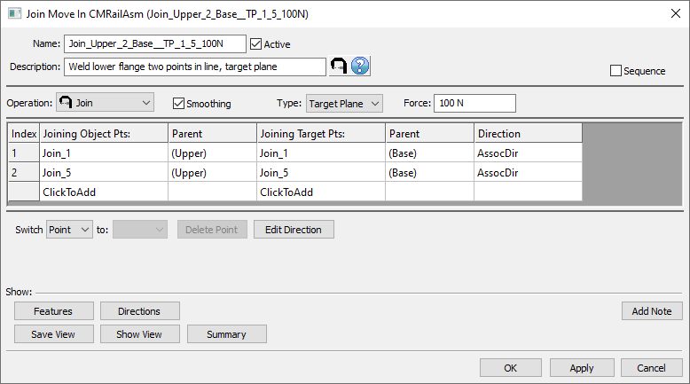
13.2 Name the move "Join_Upper_2_Base_Join_1_and_5" with a description of "Join lower flanges two points in line, target plane".
13.3 Click on the [ClickToAdd] button in the Joining Object Pts section and grab points labeled Join_1 and Join_5 on the lower
flange of the Upper.
13.4 Click on the [ClickToAdd] text in the Joining Target Pts section and grab points labeled Join_1 and Join_5 on the lower flange of the Base.
13.5 Select Smoothing check box to use Smoothing.
13.6 Use Type to toggle between Target Plane and Coincident, and select [Target Associate] for Direction.
13.7 Type 100 in the Force field. This will change the Infinite into 100N for joining force value.
13.8 Ensure that all object points correspond to the correct target points by clicking the [Features] button. If the order is incorrect utilize the Switch To drop-down to correct the order.
The completed dialog box should appear as below:

13.9 Click [OK] to close the dialog box.
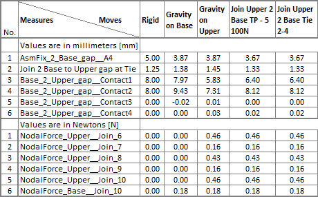
13.10 Repeat above steps to create the second join operation on the lower flange. This join will be named "Join_Upper_2_Base__Tie_2-4" and will be applied on points Join_2, Join_3 and Join_4. There is a 1.25mm design gap between the two flanges at these locations therefore the join type will be Tie. The points will be connected while maintaining the gap value (1.40mm) that results from all previous moves: Rigid, Gravity on Base, Gravity on Upper, and Join_Upper_2_Base__TP_1_5_100N .
13.11 Save the model.
Results:
The nominal values of the measurements after positioning and clamping the Upper will change due to the deformation of the parts during the join with Target Plane operation but no deformation will happen due to join with Tie operation.

>>>Your results may not match the above illustration<<<