Changing Colors
In this section, we will change the part colors. Using different colors can make it easier to differentiate between parts in the Graphics window. The part color will set the color of the points and mesh. Both the part color and point and mesh colors can be changed at any time.
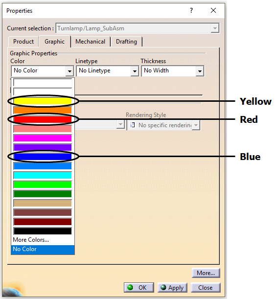
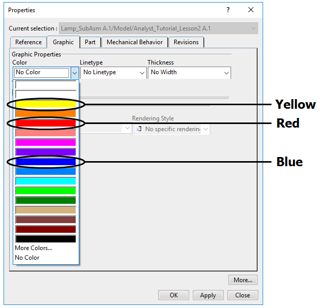
•Right-click the Headlamp in the Navigation Tree and select Properties.
•Select the Graphic tab.
•In the Color drop-down list, select Yellow.
•Click [OK] and the Headlamp color will change to Yellow.
•Repeat this process to change the Turnlamp color to Red and the Bracket color to Blue.
•Click ![]() Update Model.
Update Model.
•Double-click Bracket in the Navigation window to open the Edit Part dialog.
•Click the [Part Color] button. This will change the color of the Bracket in the Lamp_SubAsm.
•In the Color dialog, select Blue then click [OK].
•Click the [Analysis Mesh Color] button. This will change the color of the mesh in the Bracket. So far, we have not created any mesh so you will not see any changes.
•In the Color dialog, select Blue then click [OK].
•Uncheck Show Color Contour then select All DCS under HSF Color.
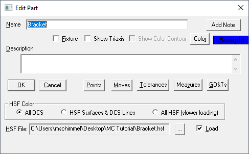
Note: HSF Color controls how a part's color is set.
![]() All DCS: The parts will have the color set by the user in the Edit Part dialog box.
All DCS: The parts will have the color set by the user in the Edit Part dialog box.
![]() HSF Surfaces & DCS Lines: The surfaces will have the same color as the HSF file and the edges will have the color set by the user in the Edit Part dialog box.
HSF Surfaces & DCS Lines: The surfaces will have the same color as the HSF file and the edges will have the color set by the user in the Edit Part dialog box.
![]() All HSF (slower Loading): Both the surfaces and the edges will have the same color as the HSF file.
All HSF (slower Loading): Both the surfaces and the edges will have the same color as the HSF file.
Show Color Contour does not work with All DCS.
•Click [OK] in the Edit Part dialog.
•Repeat this process to change the color of the Headlamp to Yellow and the color of the Turnlamp to Red.
•Right-click the Bracket part in the NX Assembly Navigator tree and choose the![]() Edit Display icon.
Edit Display icon.
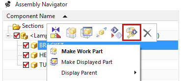
•In the General tab, in the Basic section, click the gray box to the right of Color.
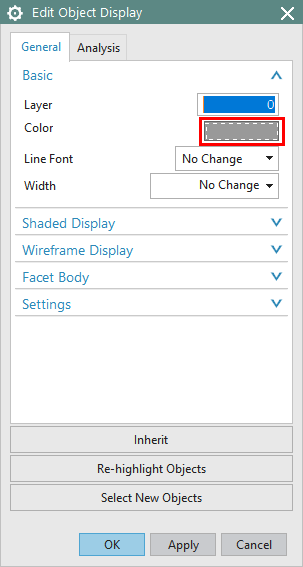
•Select Blue then click [OK] in the Color dialog.
•Click [OK] in the Edit Object Display dialog.
•Repeat this process to set the Headlamp to Yellow and the Turnlamp to Red.
•Switch to the 3DCS tab.
•Click ![]() Load 3DCS if not already loaded.
Load 3DCS if not already loaded.
•Click ![]() Update Model.
Update Model.
•Select the Bracket from the Creo Model Tree.
•Select the Render tab and click the Appearance Gallery drop-down list.
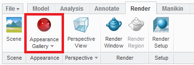
•Select the Blue color displayed in the image below to change the color of the Bracket.
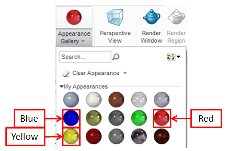
•Repeat this process to change the Headlamp to Yellow and Turnlamp to Red.
•Switch to the 3DCS tab.
•Click ![]() Update Model.
Update Model.
•Select DisplayManager from the toolbar on the left hand side and select Open Appearance Library and Pin it to the screen and then go back and select the Feature Manager Design Tree.
•Then select Solid under Appearances and select Blue and Drag and Drop it onto the Bracket part.
•Repeat this process to set the Headlamp to Yellow and the Turnlamp to Red.
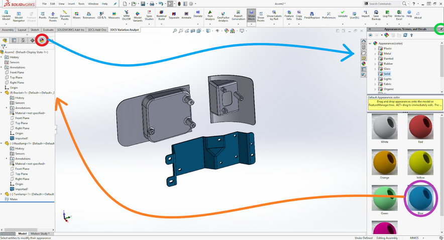
•Switch to the 3DCS Variation Analyst Tab and click ![]() Update Model.
Update Model.
Creating Scenes
A set of scenes will allow you to switch between several positions of specified parts, sub-assemblies, or for the entire assembly. For example, the parts can be exploded or reset to their original design position using a saved scene. Any assembly stage can be saved as a scene. This can also be used to maintain other settings such as part color, transparencies, or hidden parts.
•Make sure you are in ![]() Creation Mode.
Creation Mode.
•Go to the Start menu and select Mechanical Design ![]() Assembly Design.
Assembly Design.
•Find the Scenes toolbar.

•With the parts in the initial (nominal) position, click the ![]() Enhanced Scene button to open the Enhanced Scene dialog box.
Enhanced Scene button to open the Enhanced Scene dialog box.
•Select [Full] for Overload Mode
•Uncheck the Automatic naming option then enter "Design" into the Name field.
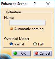
•Click [OK].
The screen background changes to green every time a scene is activated. A warning message may appear about performing moves that may invalidate analysis results. This message may appear every time the user enters a scene.
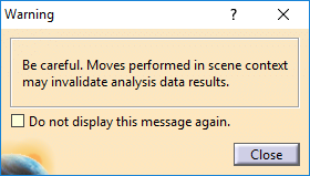
•[Close] the warning.
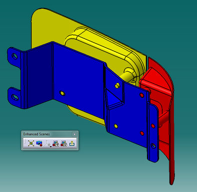
•Click the ![]() Exit Scene icon shown below in the Enhanced Scenes toolbar to save the current position of the parts and return to the model.
Exit Scene icon shown below in the Enhanced Scenes toolbar to save the current position of the parts and return to the model.
Creating Arrangements
A set of arrangements will allow the user to switch between several positions for specified parts, sub-assemblies, or for the entire assembly. For example, the parts can be exploded or reset to their original design position using saved arrangements. Any assembly stage can be saved as a arrangement. All parts must be set to 'Individually Positioned' for the arrangements to function correctly.
•Select all parts. Do this by one of the following methods:
1.In the graphics area, drag a box around all three parts.
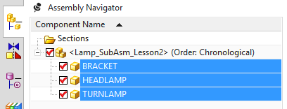
2.In the Assembly Navigator, click the first part in list then shift+click the last part in the list.
•With all parts selected, right-click one of part names in the Assembly Navigator and select Properties.
•In the Parameters tab, in the Parameters section, under Position in the Used Arrangement, select Individually Positioned.
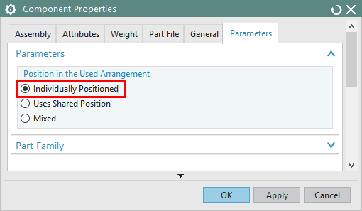
•Click [OK] to close the Component Properties dialog.
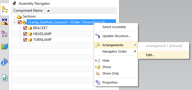
•In the Assembly Navigator, right-click Lamp_SubAsm_Lesson2 and select Arrangements ![]() Edit...
Edit...
•Select Arrangement 1 (Default) and click ![]() Rename. Rename the arrangement "Design".
Rename. Rename the arrangement "Design".
•Click ![]() New Arrangement and name it "Exploded".
New Arrangement and name it "Exploded".
•With the Exploded arrangement still selected, click ![]() Use. The completed Assembly Arrangements dialog should look like the image below.
Use. The completed Assembly Arrangements dialog should look like the image below.
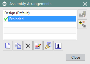
This will set the Exploded arrangement as the active arrangement. Next, when we separate the parts, the Exploded arrangement will be used to save the exploded position of the parts. The Design arrangement will be used to save the design position of the parts. The arrangements can be used to quickly switch the part positions between design and exploded.
•Click [Close] in the Assembly Arrangements dialog.