It's good practice for parts to be translated away from each other to verify all moves have been created correctly. This also makes it easier to select points and view the assembly process.
•In your Apps and Roles quadrant, select "Assembly Design".
•Drag the Compass to the Headlamp by clicking on the squarecircle at its base.
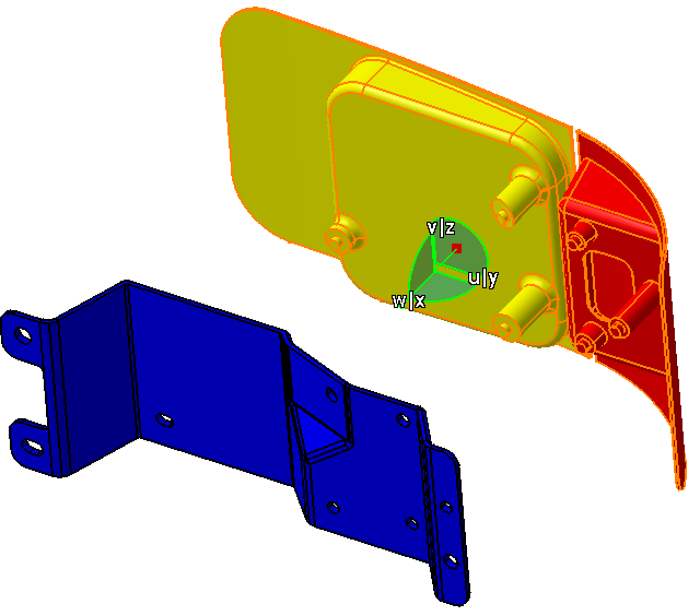
•In the Navigation Tree, highlight the Headlamp and Turnlamp (the Compass should turn greenorange).
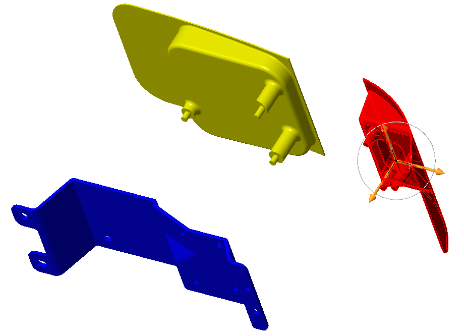
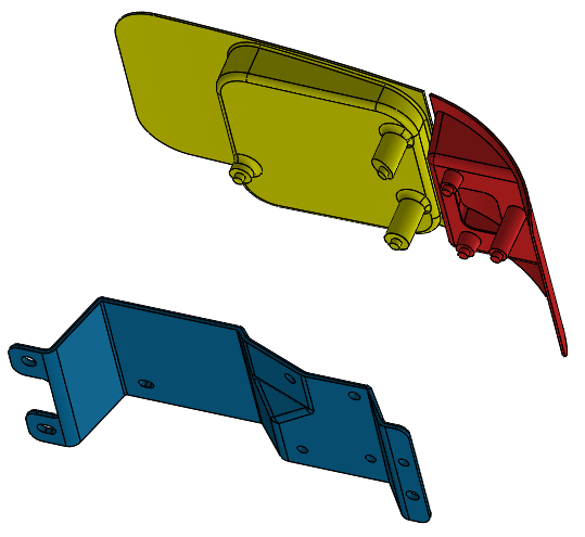
•By dragging the Compass direction, drag the two parts about 200 mm away from the Bracket (as shown in the image below).
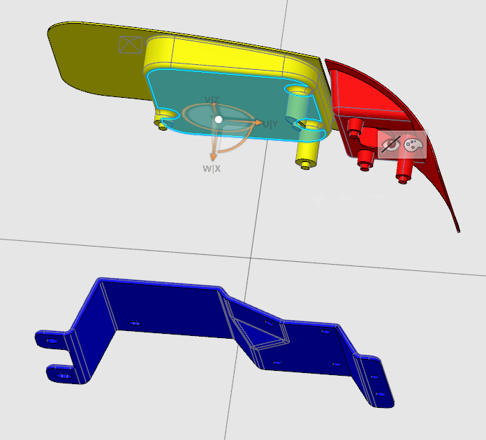
•Select only the Turnlamp in the Navigation Tree by clicking in the Graphics Window and then re-selecting it.
•By dragging the Compass direction, drag the Turnlamp about 100 mm away from the Headlamp (as shown in the image below).
•Return the compass to the corner.
For further information on this function, please go to Manipulation, or see the CATIA Online Documentation page entitled "Moving Objects Using the 3D Compass".
Note: The Translation or Rotation command may also be used to translate and rotate parts or sub-assemblies. This command will translate and rotate components by a specified increment.
•Select the ![]()
![]() Fit All In icon and then Zoom until the parts fill the graphics area.
Fit All In icon and then Zoom until the parts fill the graphics area.
•Follow the same steps as before to create a new Scene and name it "Separated".
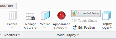
•Switch to the Model tab and click ![]() Manage Views.
Manage Views.
•In the View Manager dialog, select the Explode tab and click [New].
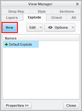
•Type "Exploded" as the name and press the Enter key to create the Exploded View.
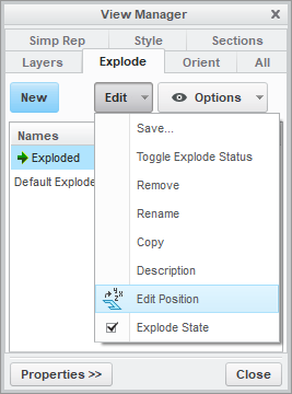
•With Exploded highlighted, click [Edit] then select Edit Position.
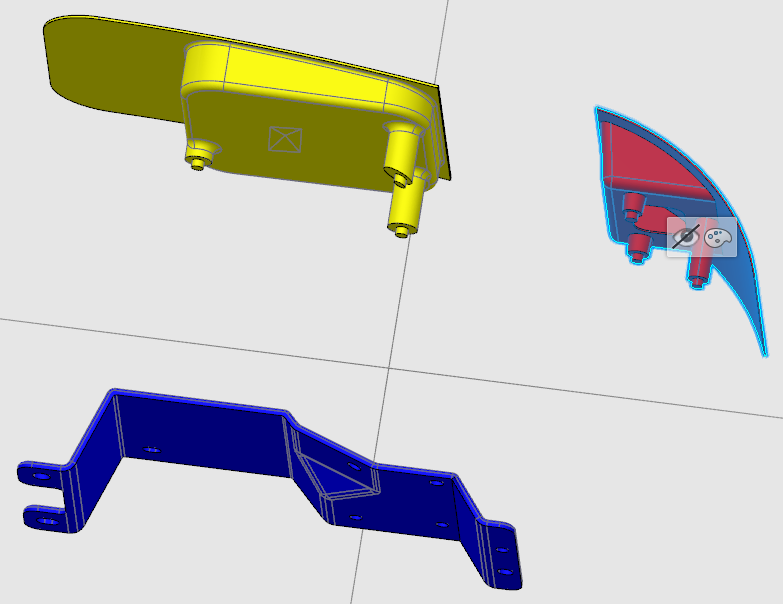
•In the Creo Model Tree, select both the Turnlamp and the Headlamp. A compass will appear on the screen.
•Drag the arrow of the compass to move Turnlamp and Headlamp about 200 mm in the X-direction away from the Bracket (as shown in the image below).
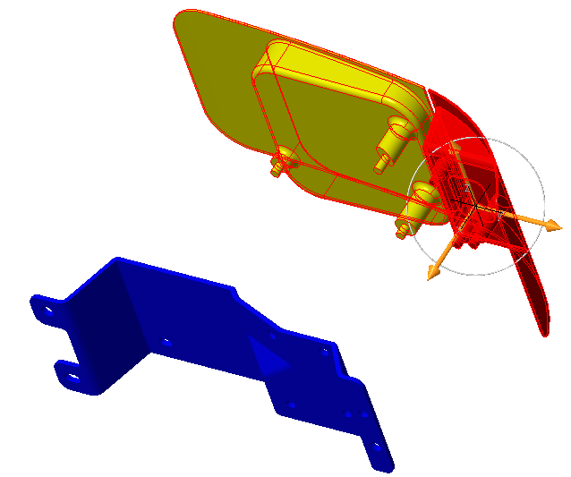
•Select only the Turnlamp.
•Drag the compass to move the Turnlamp about 100 mm in the Y-direction away from the Headlamp (as shown in the image below).
•Click the Green Check Mark in the Explode Tool tab.
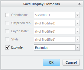
•Click [Edit] then select Save... .
•In the Save Display Elements dialog, make sure Explode is checked and Exploded is selected from the drop-down list, then click [OK].
Exploded should no longer have a "(+)" next to it and should have a green arrow to the left of it. This indicates that it is the current active Explode State.
•Click [Close] in the View Manager dialog.
In the Model tab, when the [Exploded View] button is active, the parts will be in their exploded positions. When the [Exploded View] button is inactive, the parts will return to their as assembled positions. You need to ![]() Update Model after you activate or deactivate the [Exploded View] button so that the 3DCS data stays with the Creo parts. This can be seen after adding points or features to the model.
Update Model after you activate or deactivate the [Exploded View] button so that the 3DCS data stays with the Creo parts. This can be seen after adding points or features to the model.
•Go to the Geometry tab and select Translate / Rotate ![]() Component.
Component.
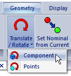
•In the Translate/Rotate dialog, click [Component] then select the Headlamp.
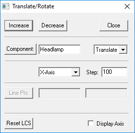
•Set the drop-down lists to Translate and X-Axis and set the Step to 100.
•Click [Decrease] twice to translate the Headlamp -200 mm in the X-direction.
•Click [Component] then select the Turnlamp.
•Click [Decrease] twice to translate the Turnlamp -200 mm in the X-direction.
•Change the direction drop-down list to Y-Axis.
•Click [Increase] to translate the Turnlamp 100 mm in the Y-direction.
•Click [Close] in the Translate/Rotate dialog.
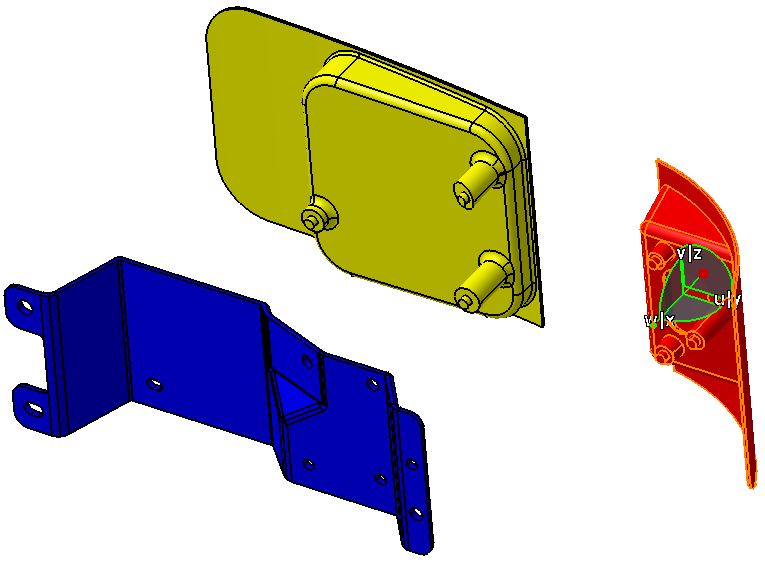
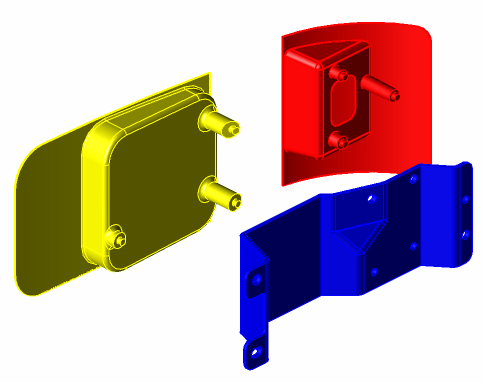
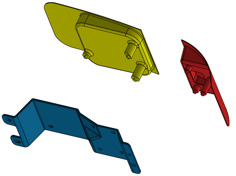
The assembly should look like the following image.
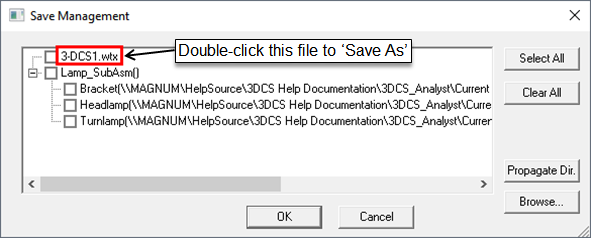
Now, we will save the model and propagate the hsf files into the same folder as the wtx file, which contains the 3DCS data.
•Click the ![]() Application Button then select
Application Button then select ![]() Save Management.
Save Management.
•Double-click the wtx file in the top row to open the Save As dialog.
•Navigate to a folder that will be easily accessible later or create a new folder on the desktop.
•Change the File Name to "Lesson2.wtx".
•Click [Save] in the Save As dialog.
•Click [Propagate Dir.] to save a copy of the hsf part files to the same folder.
Note: The files that are checked are the ones that will be saved.
•Click [OK] in the Save Management dialog. The model is not saved until you click OK.
•Right-click on the Headlamp and select the ![]() Move icon.
Move icon.
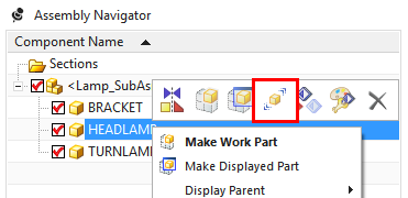
•In the Transform section, select Dynamic for the Motion type.
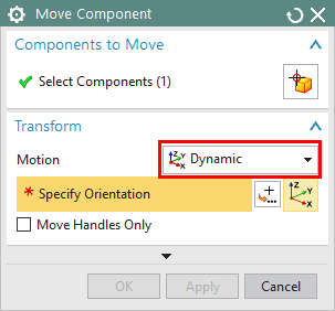
•Drag the XC arrow of the trihedron to translate the Headlamp -200 mm in the x-direction.
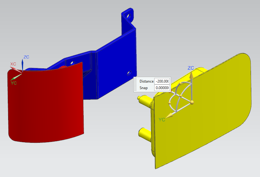
•Click [<OK>] in the Move Component dialog.
•Repeat this process to translate the Turnlamp -200 mm in the x-direction and 100 mm in the y-direction. The final part position should look like the following image.
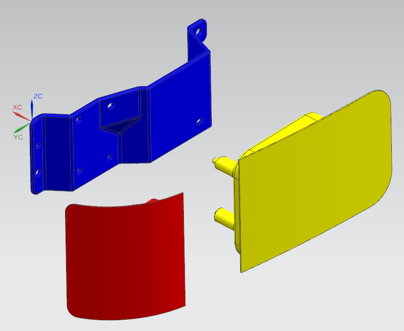
•If needed, click ![]() Fit to display all parts on screen.
Fit to display all parts on screen.
•To use the arrangements, right-click Lamp_SubAsm_Lesson2 in the Assembly Navigator then select Arrangements ![]() Design. The parts will move back to their design position.
Design. The parts will move back to their design position.
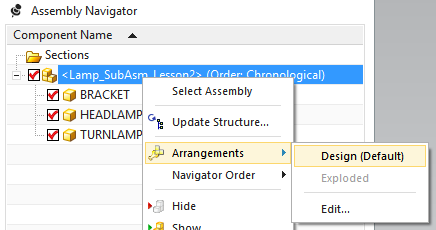
•Right-click Lamp_SubAsm_Lesson2 in the Assembly Navigator then select Arrangements ![]() Exploded to return the parts to their exploded position.
Exploded to return the parts to their exploded position.
•Click ![]() Update Model
Update Model
We must ![]() Update Model because translating the parts and using arrangements are NX functions that do not take effect in 3DCS until the model is updated. This will become evident after we create features in 3DCS.
Update Model because translating the parts and using arrangements are NX functions that do not take effect in 3DCS until the model is updated. This will become evident after we create features in 3DCS.
•Select ConfigurationManager from the toolbar on the left hand side of the screen.
•Right-click on Default from the tree under Configurations and select New Exploded View...
•In the Graphics Window, hold the Ctrl key and select the Headlamp and the Turnlamp.
•In the Graphics Window, click and drag the arrow labeled X on the compass to move the Headlamp and Turnlamp above the Bracket by about 200mm.
•In the Explode dialog on the left of the screen, select [Done] to complete Explode Step1.
The Bracket, Headlamp, and Turnlamp should now look like the image below.
•Select the Turnlamp to begin Explode Step2.
•In the Graphics Window, click and drag the arrow labeled Y on the compass to move the Turnlamp away from the Headlamp by about 100mm.
•In the Explode dialog on the left of the screen, select [Done] to complete Explode Step2.
The Bracket, Headlamp, and Turnlamp should now look like the image below.
•Select ![]() OK in the Explode dialog to complete and save the newly created Exploded View.
OK in the Explode dialog to complete and save the newly created Exploded View.
•Create a scene for this separated position. Name the scene "Exploded".
We can now use the Design and Exploded scenes to quickly switch between saved part positions.
•Right-click the Design scene in the tree and go to Design object ![]() Apply Scene on Assembly and select Apply All Position Attributes. The parts should return to the design position.
Apply Scene on Assembly and select Apply All Position Attributes. The parts should return to the design position.
•Right-click the Exploded scene in the tree and go to Exploded object ![]() Apply Scene on Assembly and select Apply All Position Attributes. The parts should return to the exploded position.
Apply Scene on Assembly and select Apply All Position Attributes. The parts should return to the exploded position.
•Go to Start ![]() Analysis & Simulation and select 3DCS Analysis to return to the 3DCS workbench.
Analysis & Simulation and select 3DCS Analysis to return to the 3DCS workbench.
•Click ![]() Update Model
Update Model
We must ![]() Update Model because translating the parts and applying scenes are CATIA functions that do not take effect in 3DCS until the model is updated. This will become evident after we create features in 3DCS.
Update Model because translating the parts and applying scenes are CATIA functions that do not take effect in 3DCS until the model is updated. This will become evident after we create features in 3DCS.
•Create a slide for this separated position. Name the slide "Exploded".
We can now use the Nominal and Exploded slides to quickly switch between saved part positions.
•Right-click the Nominal slide in the tree and select Apply Slide. The parts should return to the nominal position.
•Right-click the Exploded slide in the tree and select Apply Slide.. The parts should return to the exploded position.
•Return to the Manufacturing Simulation (Analyst_Tutorial_Lesson2) tab to return to the 3DCS workbench. (Note: Applying slides must be done in the Product tab. The change in part positions is then reflected when you return to the Manufacturing Simulation tab.)
•Click ![]() Update Model.
Update Model.
We must ![]() Update Model because translating the parts and applying slides are 3DEXPERIENCE functions that do not take effect in 3DCS until the model is updated. This will become evident after we create features in 3DCS.
Update Model because translating the parts and applying slides are 3DEXPERIENCE functions that do not take effect in 3DCS until the model is updated. This will become evident after we create features in 3DCS.
All of the 3DCS modeling data is saved with the CATProduct file. To prevent model corruption, use Save Management whenever saving your model.
•From File, select Save Management.
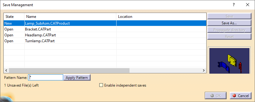
•Highlight the new Lamp_SubAsm.CATProduct file and click [Save As].
•Navigate to a folder that will be easily accessible later or create a new folder on the desktop.
•Change the File Name to "Lesson2.CATProduct".
•Click [Save].
•Click [Propagate Directory] to save a copy of the CATPart files to the same folder.
•Click [OK] in the Save Management dialog. The model is not actually saved until you click OK.
•Save the model.
•Click ![]() Save. Because this is the first time saving the model, the Save Object dialog will open.
Save. Because this is the first time saving the model, the Save Object dialog will open.
•Navigate to the User Lessons folder if not already there then click [OK] to save.
•Highlight the ![]() Share icon and select Save in the drop-down list to save the Simulation and Assembly.
Share icon and select Save in the drop-down list to save the Simulation and Assembly.
•From File, select Save to save the model.