The following steps will lead you through different functions of the Feature Creation and Model Creation toolbars. They are used to create Points, Moves, Tolerances, GD&Ts, and Measures. The toolbars contain the following icons:
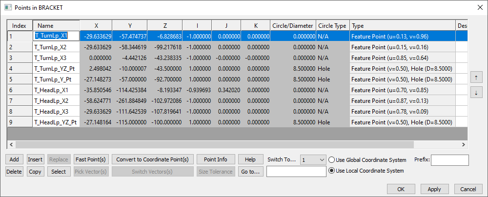
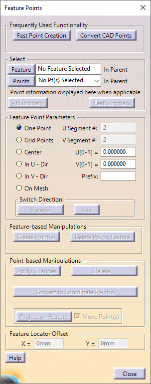
•Click ![]() Points then select the blue part named Bracket. You can select a part by clicking it in the graphics or in the tree. This will open the Points dialog for the Bracket. You can use this dialog box to create or modify Points in a part based on coordinates.
Points then select the blue part named Bracket. You can select a part by clicking it in the graphics or in the tree. This will open the Points dialog for the Bracket. You can use this dialog box to create or modify Points in a part based on coordinates.
•Select [Cancel] to close the Points dialog without applying any changes.
•Click ![]() Feature Points.
Feature Points.
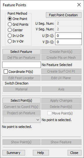
This will open the Feature Points dialog. It is used to create or modify Points that are linked to a feature on a part.
•Click [Close] on the Feature Points dialog.
Parts are constrained in 3DCS by using Moves. You can use one or more Moves to represent a manufacturing assembly process.
•Click the ![]() Moves button then select Lamp_SubAsmLamp_SubAsm_Lesson6 in the Navigation Tree.
Moves button then select Lamp_SubAsmLamp_SubAsm_Lesson6 in the Navigation Tree.
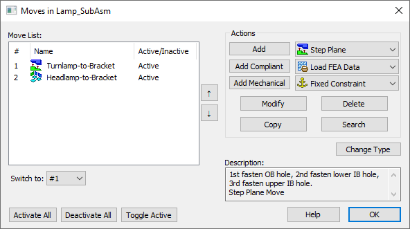
This opens the Moves dialog for Lamp_SubAsmLamp_SubAsm_Lesson6. The Move List contains all the Moves already created in Lamp_SubAsmLamp_SubAsm_Lesson6. You can modify existing Moves or create new Moves through the Moves dialog.
•Select the Headlamp-to-Bracket Move in the Move List to highlight the Move then click the [Modify] button.
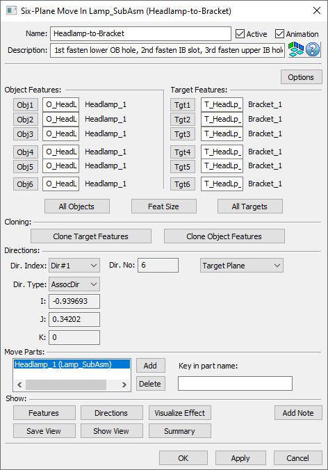
This will open the Move dialog for the Headlamp-to-Bracket move. From this dialog, you are able to define how a part gets constrained within a model. The title bar of the Move dialog will state the type of Move as well as the parent part or assembly. This particular move is a Six-Plane Move and its parent is the Lamp_SubAsmLamp_SubAsm_Lesson6 assembly.
•Click [Cancel] to close the Six-Plane Move dialog without applying any changes.
•Click [OK] to close the Moves dialog.
There are two ways to add variation to the nominal part geometry in 3DCS: Tolerances and GD&Ts. Tolerances are a basic method for directly adding variation to a part. GD&T follow the tolerancing standards from ASME or ISO rules. Typically in modeling the GD&Ts tool will be used to add variation, but we will also cover the older Tolerances tool later in this tutorial.
•Click ![]() GD&Ts then select the Bracket.
GD&Ts then select the Bracket.
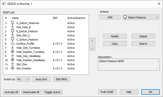
This will open the GD&T dialog for the Bracket. The GD&T List contains all the GD&Ts already created in the Bracket. You can modify existing GD&T or create new through the GD&T dialog.
•Highlight the Surface_Profile in the list then select the [Modify] button.
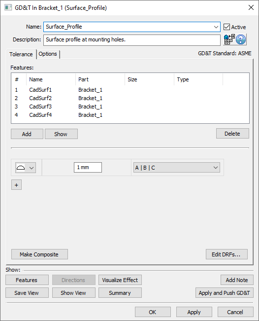
This GD&T dialog defines a surface profile Tolerance applied to features on the Bracket. The features that will deviate are shown in the Features List. The amount of variation that will be applied is set by the Range, Distribution, and Offset. The title bar of the GD&T dialog will state the type of the Tolerance as well as the parent part or assembly.
•Click [Cancel] to close the GD&T dialog.
•Click [OK] to close the GD&Ts dialog.
The outputs of a 3DCS model are defined by Measures. Measures track the amount of variation within an assembly. The amount of variation can be compared to the design objectives to check if the assembly can be produced within acceptable limits or if changes need to be made to improve the product.
•Click the ![]() Measures button then select Lamp_SubAsmLamp_SubAsm_Lesson6.
Measures button then select Lamp_SubAsmLamp_SubAsm_Lesson6.
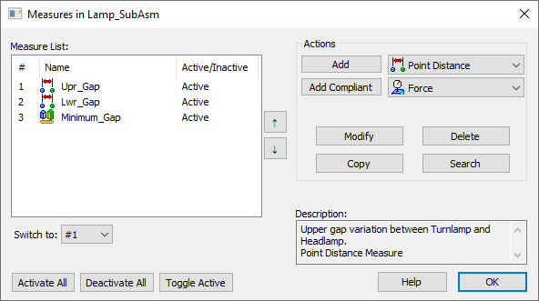
This opens the Measures dialog for the Lamp_SubAsm_Lesson6. The Measure List contains all of the Measures already created in the Lamp_SubAsm_Lesson6. You can modify existing Measures or create new Measures through this dialog.
•Highlight Upr_Gap then click [Modify].
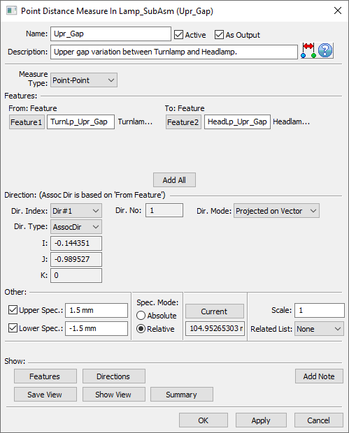
This opens the Measure dialog. This measure tracks the distance between two points, one on the Turnlamp and one on the Headlamp, along a vector. The allowable amount of variation for this measure is set by the Specification Limits. The title bar of the Measure dialog states the type of Measure as well as the parent part. This particular measure is a Point Distance Measure and its parent is Lamp_SubAsm_Lesson6.
•Click [Cancel] to close the Point Distance Measure dialog.
•Click [OK] to close the Measures dialog.
•Go to File ![]() Manage Session
Manage Session ![]() Erase Not Displayed and select [OK] in the Erase Not Displayed dialog to clear the cache of any parts.
Erase Not Displayed and select [OK] in the Erase Not Displayed dialog to clear the cache of any parts.