3DCS has the ability to read the embedded part GD&T. In this lesson, you will learn how to extract GD&T to use in the model.
If the parts were opened with Use Partial Loading selected, the PMI will not be read. The parts must be fully opened to extract the GD&T.
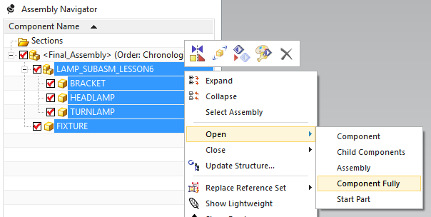
•Select all of the parts in the Assembly Navigator including Lamp_SubAsm_Lesson6.
•Right-click one of the selected parts and select Open ![]() Component Fully
Component Fully
Before we extract the GD&T embedded in the part files, we will delete the GD&T we created in Lesson 5 of this tutorial.
•In the 3DCS Model Navigator expand the Bracket.
•Right-click on the GD&Ts section of the Bracket and select Delete to delete all the GD&T associated with the Bracket.
•Repeat this process for the Turnlamp and the Headlamp to delete their respective GD&T as well.
•With the model separated, verify the mesh display is active and select ![]() Deviate.
Deviate.
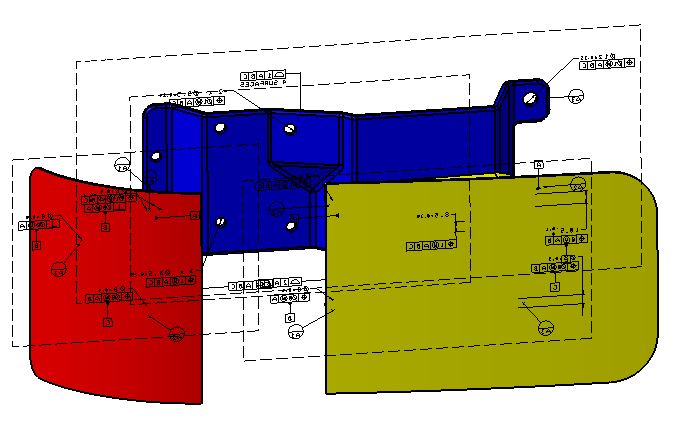
Notice that the meshed surfaces of the Bracket, Headlamp, and Turnlamp no longer deviate from their nominal location. Now, we will extract the GD&T from the individual parts.
•Click [Close] in the Deviate dialog to stop the deviation.
•Click ![]() Extract GD&T located next to
Extract GD&T located next to ![]() Update Model in the 3DCS Model Update section of the 3DCS tool bars. This will open the Extract GD&T dialog.
Update Model in the 3DCS Model Update section of the 3DCS tool bars. This will open the Extract GD&T dialog.
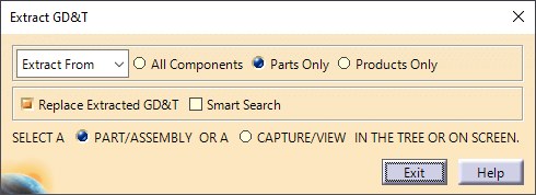
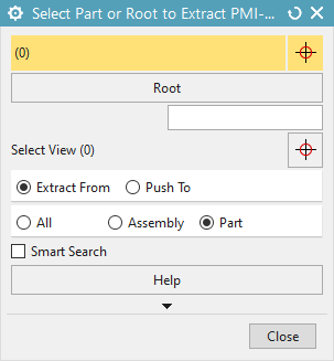
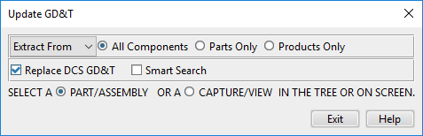
From this dialog we can choose whether we want to extract the GD&T from all the components (assembliesproducts and parts), only assembliesproducts, or only the parts. For this model we want the GD&T extracted from the parts and have no GD&T to extract from the assembliesproducts so as long as we have All Components or Parts Only selected then we will extract the part level GD&T that we want. Also we can choose whether to extract the GD&T from the CAD to the 3DCS model or push the GD&T changes from the 3DCS model to the CAD.
•Ensure that either All Components or Parts Only is selected as well as Extract From.
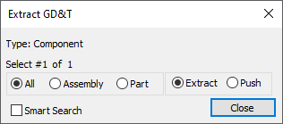
•Select Final_Assembly in the 3DCS Model Navigator to extract the embedded GD&T from all parts in the model. A message will appear stating the number of extracted GD&T callouts.
•Click [OK] to close the dialog box.
•Click [Exit][Close] to close the Extract GD&T dialog.
•Click the ![]() GD&Ts button then select the Bracket to view the imported GD&T.
GD&Ts button then select the Bracket to view the imported GD&T.
•Double-click on one of the Position call-outs in the GD&T List to view and notice its similarity to the GD&T created back in Lesson 5.
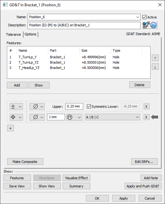
•Click [OK] to close the GD&T dialog.
•Save the model using Save Management.
•Select ![]() Nominal Build then
Nominal Build then ![]() Run Analysis. The results from using the extracted GD&T should be similar to the results from using the tolerances.
Run Analysis. The results from using the extracted GD&T should be similar to the results from using the tolerances.
•Click ![]() Separate.
Separate.