We need to tolerance the Fixture surface points for profile and the pin points for size and position.
•Select the ![]() GD&T button then select the Fixture.
GD&T button then select the Fixture.
•Select Surface Profile in the drop-down list then click [Add]. This will open the Surface Profile dialog.
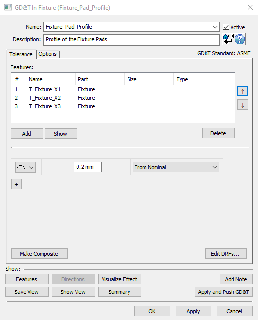
•Change the Name to "Fixture_Pad_Profile".
•Enter a Description of "Profile of the Fixture Pads."
•Click [Add] then select the points T_Fixture_X1, T_Fixture_X2, and T_Fixture_X3 in the Fixture.
•Click [Close] in the Select dialog.
•Set the Range to 0.2 mm.
•Click the Options tab and uncheck the Auto Refine check box.
The completed Surface Profile should look like the image below.

•Click [OK] to save the GD&T and close the dialog.
•Select Size in the GD&T dialog drop-down list then click [Add]. This will open the Size GD&T dialog.
•Change the Name to "Size_Fixture_Pins".
•Enter a Description of "Size of the fixture pins".
•Click [Add] then select the points Fixture_YZ_Pt and Fixture_Z_Pt in the Fixture.
•Click [Close] in the Select dialog.
•Set the Upper limit to 0.05mm.
•Click the "+" and add a Position GD&T.
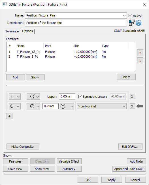
•Change the Name to "Position_Fixture_Pins".
•Enter a Description of "Position of the fixture pins".
•Add a Range of 0.2mm.
•Change the DRF to "From Nominal".
The completed Size and Position GD&T should look like the image below.

•Click [OK] to save the GD&T and close the dialog.
•Click [OK] to close the GD&T dialog.
•Save the model using Save Management.
•Show the points using ![]() Show Points if they are hidden.
Show Points if they are hidden.
•Click the ![]() Deviate button to see the variation on the Fixture points.
Deviate button to see the variation on the Fixture points.
•![]() Nominal Build and
Nominal Build and ![]() Deviate to see the variation of the Bracket on the Fixture.
Deviate to see the variation of the Bracket on the Fixture.
•Click ![]() Separate.
Separate.