The
Example Model:C:\Users\Public\Documents\DCS\3DCS_V5_8_2_0_0\3DCS CAD & Example Models\Reference Models\Tolerances\Arc Tolerance
|
Inputs:
Name |
Required |
|
Description |
Optional |
|
Point List: |
Required |
|
Center |
Required |
|
Direction |
Required |
|
Magnitude |
All parameters required |
|
Distribution |
Required |
Procedure:
1.Select a point or multiple points to deviate around on an arc.
2.Select the Center Point.
3.Specify the direction to make a plane where the points will deviate on.
4.In Rand#1, specify the Offset value. A value larger than 1 will change the arc's radius.
5.In Rand#2, specify the angle. A Range and Offset can be set. Setting the Range will deviate the arc's angle; adding an offset value will change the starting point of the Angle variation.
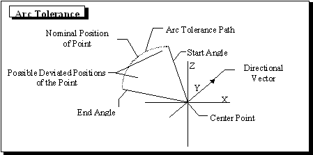
Methodology: This tolerance deviates the point in the path of an arc. The plane on which the point deviates, is created by the vector direction and a center point.
1.A Center point and vector Direction define the plane in which the point(s) deviates. The center point is also the center of the arc radius. Only one plane and center can be defined per tolerance.
2.Rand#1 controls the distance from the center point to the toleranced point. The radius of the arc is the multiple of the distance from the center point to the toleranced point and the Offset.
oA Distribution of Constant and an Offset of 1 will deviate the tolerance in a arc at its current distance from the center point.
oChanging the Distribution to Normal will show the Range field, which controls the variation of the arc radius. For example: applying Range of 1 (+/-0.5) will make the radius grow and shrink.
▪If the distance between the center point and the toleranced point varies before this tolerance is activated the varied distance will be used to calculate the Range and Offset of the arc radius.
3.Rand#2 controls the angular position of the Arc Tolerance path. The toleranced point will vary in an arc within the angular Range defined.
oIf this Range is 360 deg, the arc tolerance path will be a complete circle.
oThe Offset will define the location of the middle of the arc. The arc tolerance path will be offset from the toleranced point's current position according to the right hand rule.
4.The point deviated about the center point by the magnitude is rotated from the start angle to a random angle range. The random angle range is determined by the angular range (plus & minus), distribution, sigma, truncation and scale values. The angle is perpendicular to the direction vector.
Parameters: Most parameters that are to be defined in the Arc Tolerance are specified under Common Parameters. Center is required to set the center of the arc. Mode and Direction have specific denotations for this tolerance.
Center: The Center button defines the center of the arc to which the tolerance is applied. Clicking on this button brings up the Graph window and lets you click on the point. Once the point is defined the point name along with its part is displayed.
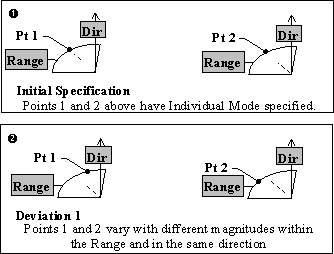
Mode: The Mode option lets you specify different combinations of magnitude and direction for greater flexibility. The Mode option has two choices: Individual Mode and Group Mode.
Individual Mode: When Individual Mode is specified, each point in the list that is associated with the tolerance varies:
•With different magnitudes in the specified range.
•On the same plane.
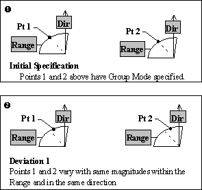
Group Mode: When Group Mode is specified, each point in the list that is associated with the tolerance varies:
•With the same magnitudes in the specified range.
•On the same plane.
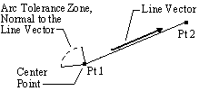
Type In Method: Varies a point in the path of an arc on a plane normal to the vector specified.
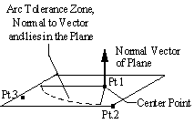
Two Point Method: Varies a point in a direction normal to the vector of the line segment chosen. Select a line segment (2 points) normal to the plane of the arc path.
Normal Direction Method: Varies a point in a plane parallel to the three points chosen. Select 3 points to specify a plane. The point will vary in a plane located at the center point parallel to this plane.