The
|
Supported features to use in this tolerance:
1. ![]() Coordinate Point as a Hole
Coordinate Point as a Hole
2. ![]() Coordinate Point as a Pin
Coordinate Point as a Pin
3. ![]() Feature Point
Feature Point
4. ![]() Feature Point on a Hole
Feature Point on a Hole
5. ![]() Feature Point on a Pin
Feature Point on a Pin
6. Entire features such as surfaces, edges, features of size. When the feature is selected, the deviation applies to all points associated to that feature.
1.Deviation method - will import CMM data into a model as a tolerance input and deviate the selected points based on this input.
There are two types of files that can be used with this method:
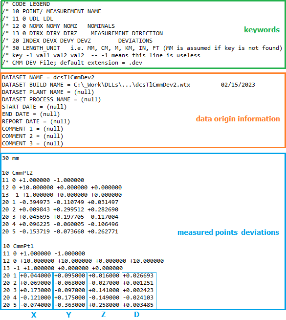
1.1. DEV file - a text file with the file extension *.dev. The file will show measured sample values for a set of points in 3 columns and can be opened with Notepad (.dev). The columns show each direction (X, Y, Z) variation. (Please see Measurement Generator for creating multiple Point-Nominal measures).The file has the following format:
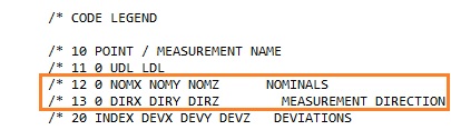
a.Keywords that explain the entries for measured points. Explanation for each line:
10 POINT / MEASUREMENT NAME
The computer program searches for the number "10". The name of the deviated point is entered in the field following "10". The "*.dev" file may not contain data for two points with the same name. If a point name is repeated the tolerance only uses the first set of data.
11 0 UDL LDL
The computer program then searches for the number "11" and skips a field - the "0" is used here only as a placeholder for the field that is skipped and has no other significance. UDL and LDL are the upper and lower spec limits on the point named above. These values are not used with the Capability tolerance routine.
12 0 NOMX, NOMY, NOMZ NOMINALS
NOMX, NOMY, and NOMZ are the nominal coordinates for the point along the X, Y and Z axes. "0" is simply a placeholder as explained above. These values are not used with the Capability tolerance routine.
13 0 DIRX DIRY DIRZ
DIRX, DIRY and DIRZ are the magnitude components of the surface normal vector for the point. Again, "0" is a placeholder. These values are not used with the Capability tolerance routine.
20 INDEX DEVX DEVY DEVZ DEVIATIONS
INDEX is the index number for the data points. DEVX, DEVY and DEVZ are the deviations from nominal along the X, Y and Z axes for the data points. These values are the ones used with the Capability tolerance routine.
30 LENGTH UNIT i.e. MM, CM, M, KM, IN, FT (MM is assumed if key is not found)
Displays the units used in the *.dev file.
b.Data origin information - shows where the information comes from along with the 3DCS model (*.wtx file).
c.Actual deviations for each measured point - the tolerance input used to deviate the selected points.
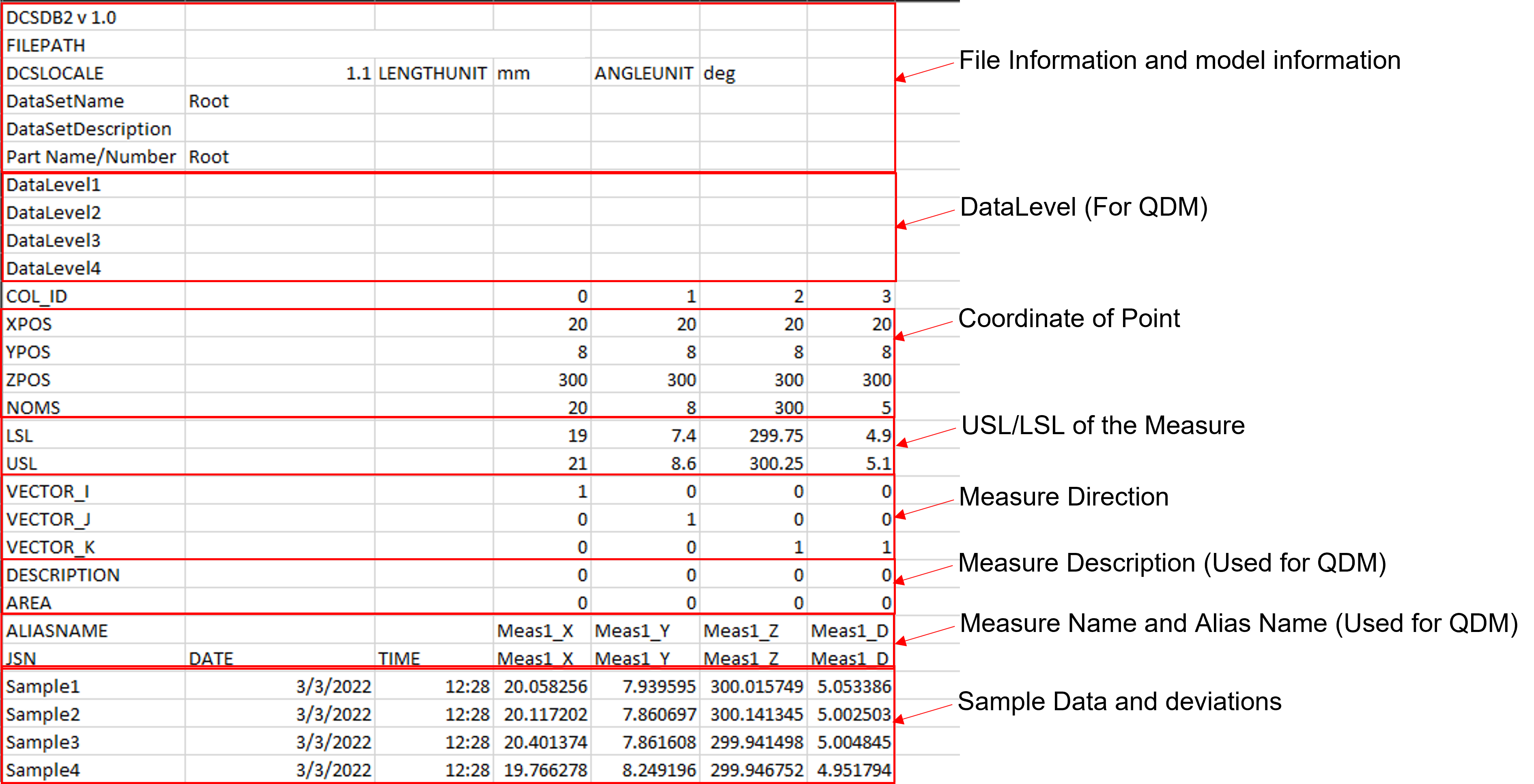
1.2. CSV file - a file called (DCSDB2) with a *.csv extension. The format for the DCSDB2 file is shown below and more information about it can be found here: QDM DB2
How to create a Capability Tolerance for Deviation:
1.For 'Type' select Deviation.
2.Add Object Points to be varied by this tolerance.
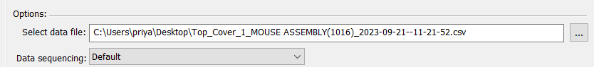
3.Select data file to be used: the *.dev or the *.csv.
4.Data sequencing options:
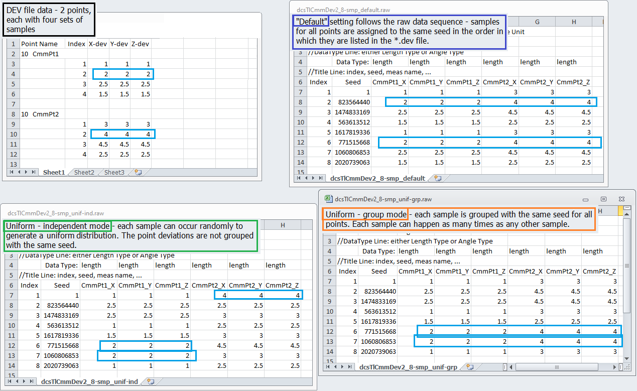
a.Default - the sample data is to be used in the sequence in which is displayed in the data file.
b.Uniform distribution group mode - the sample value is to be applied based on a uniformed-distribution-control sampling sequence in group-mode: all CMM data points are grouped with the same sampling sequence. Basically, every sample has an equal chance of happening and the same sample is applied for all measured points at the same time.
c.Uniform distribution independent mode - the sample value is to be applied based on a uniformed-distribution-control sampling sequence in individual-mode: each CMM data point has its own sampling sequence. In other words, every sample has an equal chance of happening but different samples are applied to individual measured points.
The image below shows an example of sample selection for the three options:
d.Power function distribution group mode - using the Power Function formula to apply the distribution using one random number per deviation.
e.Power function distribution independent mode - using the Power Function formula to apply the distribution using N random numbers per deviation. See Power Function for more details.
Use Data Buffer (defaulted off) - when using a data buffer all data from the data file will be loaded into a region of memory, so it is available for use. The purpose is to speed up the process. When sample number is very large (>1,000,000), the data buffer could run out of memory, so it is not recommended for a very large number of samples.
Use Sigma Range (defaulted off - Uses Min-Max Range): This option will calculate the STD from all samples in the DCSDB2 or DEV file to calculate Sigma Range.
Select Sample (defaulted off) - this option is used to support the DOE analysis. When the Selected sample is activated the user can type the sample number to be used and therefore only the x, y, z values for that samples are read. If measured, a constant distribution with a Mean value is generated for the toleranced points. The Mean value equals the selected sample x, y, or z value.
Output:
•Simulation: Deviate each feature based on the deviating data from the data files. When the simulated sample number is larger than the existing data number, the data is used cyclically.
•Sensitivity:
oContributor number is equal to 3*(number of features); Each feature will have three contributors for X, Y, and Z deviations;
oExtracted range and offset are directly calculated from data; it is not calculated for standard deviation and mean because range and offset are more important for HLM type analysis.
Notes: •During simulation the data points will be used in the order they appear in the "*.dev" file; and left to right in the "*.csv (DB2)* file. The sequence will be repeated if the number of simulations being run exceeds the number of data points. •This routine supports the HLM results. •Each feature in a new CMM Data tolerance will have three contributors; one each for the X, Y, and Z deviations. •The range and offset used in the HLM are directly calculated from data rather than calculating a standard deviation and mean from the data. •Mode is ignored for all CMM Dev-type routines •When running multi-thread, the dev file is loaded once and then copies are made for each thread. The purpose is to store the dev file data to be pulled faster when running the HST and HLM.
Data files assumptions: •Each Point Name appears only once, i.e. the subsequent list of the same point is ignored; •Multiple DEV or CSV files are allowed; •The features listed should have the unique name. If a feature name is duplicated, only the first feature gets the deviation; •At this time, the data in the files are not loaded into memory. Instead, the data file position is saved for each data point.
Measure Requirements Setting up measures to use in CMMDev or DCSDB2 files are required to have "_X, _Y, _Z, _A" (A = Associated Direction) for linear measures, and "_D" for Circle Diameter measures. Here is how 3DCS calculates the Range and Offset of each Point: •Each Point's XYZ values are calculated separately. •Range = Max - Min •Offset = 0.5*(Max + Min)
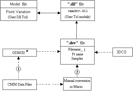
A "*.DEV" and/or a *.CSV (DB2)* file may be generated directly from QDM-3D, a software tool for generating plant data reports. To bring in simulation data from another model, 3DCS can be run in Batch Mode and a "*.dev" file exported. Please see Analysis Batch Mode for more information. The following graphic illustrates the sources of the "*.dev" file and its links to the model.
* QDM3D is a data analysis product, available from DCS.
|
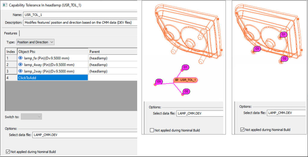
2.Position and Direction method - used to modify features' position and direction based on the CMM data (DEV files). It will update the point(s) coordinates and vector direction to match the values specified in the *.dev file. This is the same DEV file as shown above.
Process:
1.For 'Type' select Position and Deviation.
2.Add Object Points to be varied by this tolerance.
3.Select data file to be used: the *.dev.
4.Do not apply during Nominal Build check box - is used as the flag for Nominal-Build action.
•Leave un-checked if the position and direction will be modified during nominal build;
•Activate the check-box if there is no action during nominal build - the points will not move during Nominal Build, only during Deviation or in the Monte Carlo Analysis (shown by the Mean value).
Output:
•Simulation: each feature position and direction will be modified during each simulation step.
•Sensitivity: contributor number is equal to 1.
3.Mean and Sigma method - in this case only Mean shift and Standard Deviation data will be read into the model. Linear tolerances with normal distributions will be created using the extracted data. Future versions of this routine may extract curve fit info from the *.csv file and use Pearson or Weibull distributions to create non-normal tolerances.
Process:
1.For 'Type' select Mean and Sigma.
2.Add Object Points to be varied by this tolerance. If a point is selected twice it will be deviated twice with a different random value each time. Therefore, the mean shift will double and the point will vary the RSS (root-sum-of-squares) of the two standard deviation inputs.
3.Select data file to be used: a *.csv file which contains the Mean, Nominal and Sigma of a point along vectors X, Y and Z. It will contain the data to be imported in the following format, where T_TurnLp X1 and T_TurnLp X2 are the names of the points to be varied.
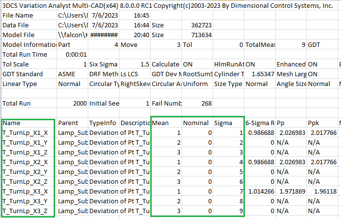
For each point with point name "T_TurnLp X1", the *.csv file contains three measurement names, T_TurnLp X1_X, T_TurnLp X1_Y, and T_TurnLp X1_Z. If one of the measurements is missing in the *.csv file, the point will not be deviated in the missing direction.
1.Add measurements for the points that will be included in the *.csv file, in X, Y, and Z directions (Measure Generator can be used)
2.Run Monte Carlo Analysis
3.Save Monte Carlo Analysis As... Statistics Row v4x(*.csv)
4.Populate the file with measured values for Mean, Nominal and Sigma.
CSV file creation from QDM:
CMM data can be imported into QDM. A *.csv file may then be exported from QDM in the correct format. 3DCS simulation data can be exported directly using the File Menu: Save Simulation As... / Stat v4x option. A text file may be edited by a macro or manually to create the *.csv file.
If using QDM, please see the QDM Help Manual for more information on importing and exporting data.
Notes: •Ensure the point names in the tolerance and the point names in the *.csv file(s) correspond (if different, the data cannot be read). •No directions or random numbers need to be specified in the Capability tolerance dialog. Random numbers are created within the routine itself. No control of seed is possible under this structure. •More than one tolerance may be linked to the same "*.csv" file. This may be necessary if the "*.csv" file contains data for more than one part. If the same point is selected in two tolerances, it will be deviated twice with a different random value each time.
|
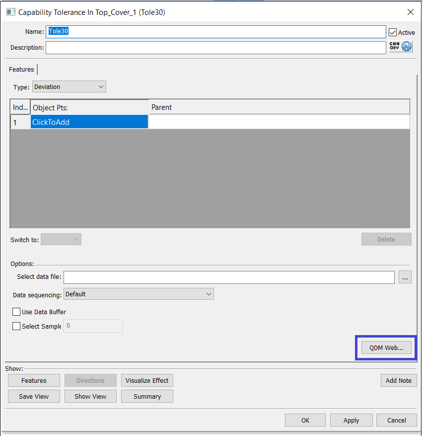
QDM Web: The QDM Web button allows bringing data from the QDM Web database directly to the Capability Tolerance in 3DCS.
Note: It is required to have a QDM Web login, to use this function in 3DCS. Please visit the DCS Website to learn how to get QDM Web.
Procedure:
1.Click the QDM Web button from the Capability Tolerance dialog.
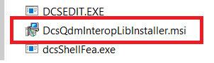
2.Doing so will prompt the user to install an application from the installation folder. This application will need to be manually installed by the user.
C:\Program Files\DCS\V5_8_2_0_0\bin\DcsQdmInteropLibInstaller.msi
C:\Program Files\DCS\V5_8_2_0_0\Application\DcsQdmInteropLibInstaller.msi
C:\Program Files\DCS\V5_8_2_0_0\win_b64\code\bin\DcsQdmInteropLibInstaller.msi
C:\Program Files\DCS\V5_8_2_0_0\bin\DcsQdmInteropLibInstaller.msi
C:\Program Files\DCS\_8_2_0_0_8_2_0_0\win_b64\code\bin\DcsQdmInteropLibInstaller.msi
C:\Program Files\DCS\V5_8_2_0_0\DcsQdmInteropLibInstaller.msi
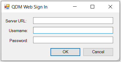
3. Now click the QDM Web button to open the QDM Web Sign In dialog and populate the Server URL, User name, and Password fields:
4. This will launch the Open Web Template dialog which will allows the user to select the data from the QDM Web by selecting the Data Source, Subsystem, Device, and Inspection Program Name.
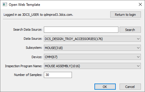
5. Once all the sections are filled, hit OK to generate the *.csv (DCSDB2) file for the extracted data and select the file location to be saved in.
6. The generated *.csv will now be automatically displayed under the Select data file section. This data will now be used in the Monte Carlo and the Contributor Analysis.