The ![]() Angle Constraint locates features to be rotated apart from one another so that the angle between them is the specified value. It uses the true angle between features except in certain cases. If the Angle move follows a Revolute, Cylindrical, or Torus and Cone move, and if it acts as an anti-rotate to the move, then it will use the angle projected in the plane normal to the axis of rotation.
Angle Constraint locates features to be rotated apart from one another so that the angle between them is the specified value. It uses the true angle between features except in certain cases. If the Angle move follows a Revolute, Cylindrical, or Torus and Cone move, and if it acts as an anti-rotate to the move, then it will use the angle projected in the plane normal to the axis of rotation.
Feature Specification
Object and target features can be any of the following combinations.
Object Features Target Features
One feature to define an axis or One feature to define an axis or
One pair of points to define an axis or One pair of points to define an axis or
One feature to define a plane or One feature to define a plane or
Two features to define a slot/tab centerplane or Two features to define a slot/tab centerplane or
One point to define a plane One point to define a plane
Procedure
The angle constraint can be created for a variety of model applications, but the basic procedure is as follows.
STEP 1 Feature Tab:
Click in the Object Features box and select one or two features from the part(s) to be moved.
Click in the Target Features box and select one or two corresponding feature(s) of the target part(s).
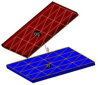
An example is shown below with two planar surfaces set at an angle of 25 degrees.
STEP 2 Move Parts Tab:
Parts should automatically be added to Move Parts based on the Tree structure of the model. Verify that these are the desired parts. Only two parts can be added to this list. The first part corresponds to the Object features and the second part corresponds to the Target features.
STEP 3 Settings Tab:
Set Angle Offset to the value desired for the angle between features.
If points have been selected in the feature lists, be sure to check the desired Use Point As setting.
Update other settings as desired.
Also See