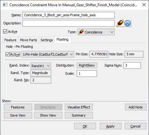
The 3DCS Mechanical moves (constraints, joints, and kinematics) have many parameters in common. When a Mechanical Move is selected, the following dialog box will be displayed. For an explanation of the common fields found in most of the Mechanical moves, see below. Please see the individual move sections for additional information.
Within this section:Move Common Paramenters Features tab Settings tab Floats tab
|
Common Parameters
Name: A name is required for the move.
Description: Use this optional field to provide a more detailed description of the move.
Active: The move can be turned on or off by toggling this button. When not selected, the move will not be applied in the model.
Type: The list menu allows user to change the type of Constraint or Joint move. Example: using Copy and Paste a move, then switch the move to a different type within the dialog.
Summary: Opens a Summary Information window listing the move parameters for the move. Select OK to close the window. Select Save as File to save the data in text format.
Features: Displays features in graphics window. Click Close to close the view and return o the Move dialog.
Save View: Saves the current screen view as the view for the selected move to be used during report generation.
Show View: Reverts the graph window back to the view that was last saved using the Save View button.
Note: Opens a Word document where the user may write notes for that move.
OK: Saves and closes the move.
Apply: Applies any changes, saves the move and keeps the dialog open.
Cancel: Closes the move without saving.
Features Tab: In this tab, the select in the Object Features and Target Features for the move. Once the move dialog opens, start selecting the features to be used in the Object or Target fields. The software will automatically switch from the object field to the target field.
•To remove a feature from the Object or Target fields, click on a feature and click the [Delete] button.
•If a point is selected, then the move will use its location and direction.
•If an CadEdge is selected, the move will use its Feature Locator Point and the Edge Direction.
•If a feature is selected, the move will use its Feature Locator Point.
The Move Parts tab specifies all parts involved with the move. This list will be automatically filled with the parts or sub-assemblies to be positioned based on the selected features. Users can manually add to this list by clicking the Add button and selecting parts in the graphics window. The part containing the "object" feature(s) must be listed first and the part containing the "target" feature(s) must be listed second.
If incorrect parts show up, highlight the unwanted part and click the Delete button.
Settings Tab:Many options can be chosen to more accurately represent a specific mechanical move. Specify directions, offset, angle, conditional rules, and solution options here. Defaults are shown below.
Target Direction: Against moves the object and target features so that their directions are opposed. Align moves the object and target features so that their directions are the same. Set in NB generally moves the parts to whichever direction minimizes their "flipping." when Nominal Build and then shows that direction in this dialog whether Against or Align. when the user have the Target direction in "Set in NB" after the user Nominal Builds it changes to either Against or Align in the dialog. This is the default setting.
Conditional Logic: Turns the move on or off based on whether the selected measure is in-spec or out-of-spec.
Contact Options: Internal aligns the features so that one is within the other. External aligns the features so that one is outside the other. Default moves the parts to one of the two conditions.
Planar Offset: Applies an offset between the features being moved if applicable.
Angle Offset: Applies an angle between the features being moved if applicable.
Solution Options: Exact aligns the features perfectly if possible. Manual Box aligns the features within a box defined by the Manual Box Size.
Manual Box Size: The size the of the box being used by the Solution Option if applicable.
Use Point As:
The [Use Point as] setting allows users to change how the points are treated. (Only available for Coincidence, Contact, Angle, and Offset Constraints).
•If a point has a circle and it is used in a Mechanical move, then by default the point is treated as a cylinder.
•If a point does not have a size and it is used in a Mechanical move, then by default the point is treated as a plane.
•The setting applies to both the object and target features. Therefore, in the previous release, if points were selected as the object and target features in a constraint-type move, then the move could only be a plane-plane or a hole-pin move, even if only one of the points had a circle defined. With this setting, more options are available, such as: a pin to plane move.
Skip Solver: Does not invoke the mechanical solver when this move is activated. Another move later in the sequence will need this option checked. Checking this option may speed up nominal build and model simulation time.
Drop DOF:
•No assumes the parts are perfectly constrained.
•Yes assumes the parts can be over-constrained.
Floats tab: If features-of-size are selected as features, floating variation can be defined in this tab. From the drop-down list, select a desired Hole-Pin pair; their sizes will be displayed to the right of the drop-down. Check the box labeled Active to activate the hole-pin float.
Users can also deactivate floats when a move has been created. Go to the 3DCS Preferences |
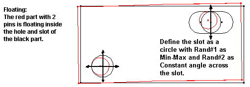
Floating describes how a pin moves within a hole or slot. It is necessary to model floating in an assembly because often a large part of the assembly variation originates from the play or floating of assembly or fixture pins within their mating holes. The maximum amount of float between a pin and hole is the difference between their diameters. Since most holes and pins have a size tolerance, their diameters vary and the amount of float varies accordingly.
3DCS first determines which matching pairs of objects and target points have holes and pins (or slots) associated to them. The pull-down menu lists all the Hole-Pin and Slot-Pin match-ups for the move. In the Move Options dialog box shown above, there is a match-up between object point (O4) and target point (T4). If this match-up of points were to be used more than once for defining the move, the Hole-Pin match-up would only show up once in the Move Options dialog box.
When a check is present in the Active check-box, the pin is allowed to float within the hole according to the method specified.
Sigma Number: The multiplier for the Standard Deviation value(s). This value is multiplied with the Standard Deviation(s) to define the range of the distribution. The Sigma value is an integer between 1 and 8. By default the multiplier is set at 3. This specification is required for Normal, Weibull, Step, Left Skew, Right Skew, Open Up and Open down distributions.
Scale: The Scale field is used to specify a multiplication factor. For instance if the user specifies 2, the tolerance is multiplied by a factor of 2. The default is set at 1.
Offset: The deviation from the nominal. The default is 0o.
Min Truncation: Truncation means to cut off at a certain point. Min Truncation means to cut the distribution at a particular low end point. The default is 0o which means no truncation.
Max Truncation: The value by which the maximum angular tolerance needs to be truncated. The default is 360o (no truncation).
Rand Index: Rand#1 (Magnitude):
Magnitude describes how far from its nominal center-line it will float. The distribution specified is spread across the diameter of the possible float range. If the Magnitude distribution is specified as Constant, the pin will always float to the edge of the hole. However for a slot, a constant magnitude will always float the pin to only one edge of the slot. For the pin to float to both sides of the slot, a BiMode distribution must be specified.
The different types of distributions are outlined in Distributions.
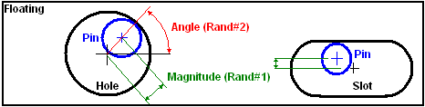
Rand Index: Rand #2 (Angle (Degrees)):
The Angle parameter specifies the angle range for the Pin to float inside its matching Hole. For a pin to float randomly (at any angle) inside a hole, a range of 360 degrees with a Uniform distribution should be specified.
Sometimes it is necessary to model a manufacturing process where the pin is more likely to float to the top side of the hole due to the effects of gravity. Then a smaller angle range (perhaps 60 degree range with an offset of 90 degrees) would float the pin in the more accurately.
The user should verify that the part is floating properly by using zoom-in to examine the Hole-Pin match-up and then using the Sweep or Deviate functions to animate the parts. See Deviate/Sweep.
•Slot-Pin matchups do not have an Rand#2 because they do not float at any angle, only a magnitude.