The ![]() Offset Constraint locates the features to be parallel (if applicable) and separated by an offset value as specified by the user. This constraint separates parts or features at a certain set distance and holds that distance as the model is assembled.
Offset Constraint locates the features to be parallel (if applicable) and separated by an offset value as specified by the user. This constraint separates parts or features at a certain set distance and holds that distance as the model is assembled.
Feature Specification
Object and target features can be any of the following combinations.
Object Features Target Features
One spherical feature or One spherical feature or
One point to define a center or One point to define a center or
One feature to define an axis or One feature to define an axis or
One pair of points to define an axis or One pair of points to define an axis or
One feature to define a plane or One feature to define a plane or
Two features to define a slot/tab centerplane or Two features to define a slot/tab centerplane or
One point to define a plane One point to define a plane
Procedure
The offset constraint can be created for a variety of model applications, but the basic procedure is as follows.
STEP 1 Feature Tab:
Click in the Object Features box and select one or two features from the part(s) to be moved.
Click in the Target Features box and select one or two corresponding feature(s) of the target part(s).
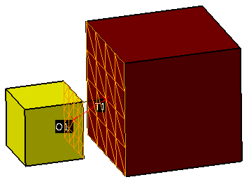
An example is shown below, where the two planar surfaces are offset by 20mm based on the indicated direction (small black arrow.) The offset is not based off of the absolute distance between the geographic centers (red x's and red line.)
STEP 2 Move Parts Tab:
Parts should automatically be added to Move Parts based on the Tree structure of the model. Verify that these are the desired parts. Only two parts can be added to this list. The first part corresponds to the Object features and the second part corresponds to the Target features.
STEP 3 Settings Tab:
Set Planar Offset to the value desired for the distance between features.
If points have been selected in the feature lists, be sure to check the desired Use Point As setting.
Update other settings as desired.
Also See