The
See Also: Common Parameters
|
Feature Specification: Object and target features can be any of the following combinations.
Object Features |
Target Features |
One Feature to define an Axis |
One Feature to define an Axis |
A pair of Points (2) to define an Axis |
A pair of Points (2) to define an Axis |
n amount of Features to define a plane |
N'th amount of Features to define a plane |
n amount of Points to define a plane |
N'th amount of Points to define a plane |
One to Two Points |
Edge or Point Group defined as an edge |
n amount of Slots or Tabs |
N'th amount Slots or Tabs |
More than 2 points defined as Curve |
More than 2 points defined as Curve |
3 or more mesh nodes in edge not in straight line is defined as Curve |
3 or more mesh nodes in edge not in straight line is defined as Curve |
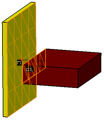
Procedure - Planar Features: To create these moves, select object and target features that represent the desired combination. The contact constraint can be created for a variety of model applications, but the basic procedure is as follows.
1. Feature Tab:
•Click in the Object Features box and select one or two features from the part(s) to be moved.
•Click in the Target Features box and select one or two corresponding feature(s) of the target part(s).
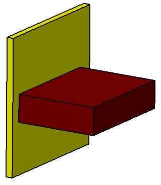
An example is shown below, where the two planar surfaces will be moved together so that they touch.
2. Move Parts Tab: Parts should automatically be added to Move Parts list based on the Tree structure of the model. Verify that these are the desired parts. Only two parts can be added to this list. The first part corresponds to the Object features and the second part corresponds to the Target features.
Contact Move on Curves
|
|
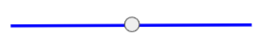
Point on Line (2 Points determines a line) Target Features: two points or an edge that contains two points. This retains 4DOF - 3 Rotations and 1Translation |
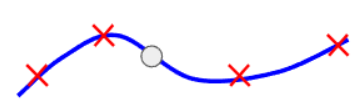
Point on Curve (Spline or at least 3 points)Target Features: 3 or more points. This retains 3DOF- 3 Rotations |
Following a Curve
Set up - 2 rotation parts
Track Part
1.Create track
a.CAD edge curve as Target
b.Feature Points > Grid> number of points, say 100
c.Create Point Based Feature
i.No Check – Convert to feature points
ii.Edge
iii.Create Point Based Feature
iv.Name track
ii.Point Part as Object
1.Create point, name point, to follow track
iii.Rotation center points are parallel
iv.Track is perpendicular to rotation centers
b.2 Axle parts
i.Rotation part centers rotate around axle parts
c.First point of track aligns with point
2.MM Steps
a.Axle Parts are Fixed
b.Kinematic Motion Rotates Track Part
i.Motion steps
1.Number of points is OK
2.Beg Pos: 0
3.End Pos: Arc length of track
ii.Feature
1.Center of Rotation – Track Part center
2.Direction Track Part Center
iii.Move Parts
1.Track Part
2.Track Part Axle
c.Contact Constraint
i.Object - Point Part point
ii.Target – Track Part track
d.Coincidence constraint
i.Point Part center to Point Axle center
e.Use Kinematic Animation
f.