This section will walk through moving the Turnlamp to the Bracket. We will use a Step-Plane Move, which follows the 3-2-1 locating scheme, to fully constrain the Turnlamp's six DoF. The locators are determined by the contact surfaces of the parts. The Turnlamp will be located using three surfaces and two pins. One of the surfaces is offset, or stepped, from the other two but all three surfaces have the same direction which allows us to use the Step-Plane Move type. If the primary planes did not have the same direction, we would have to use the Six-Plane Move as we will see later when moving the Headlamp to the Bracket. The pins will control the directions perpendicular to the primary plane direction. There are actually three pins that can locate the Turnlamp but we will ignore one until later in the tutorial.
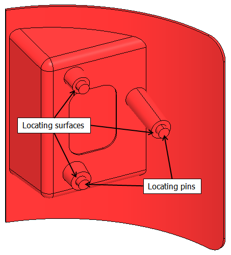
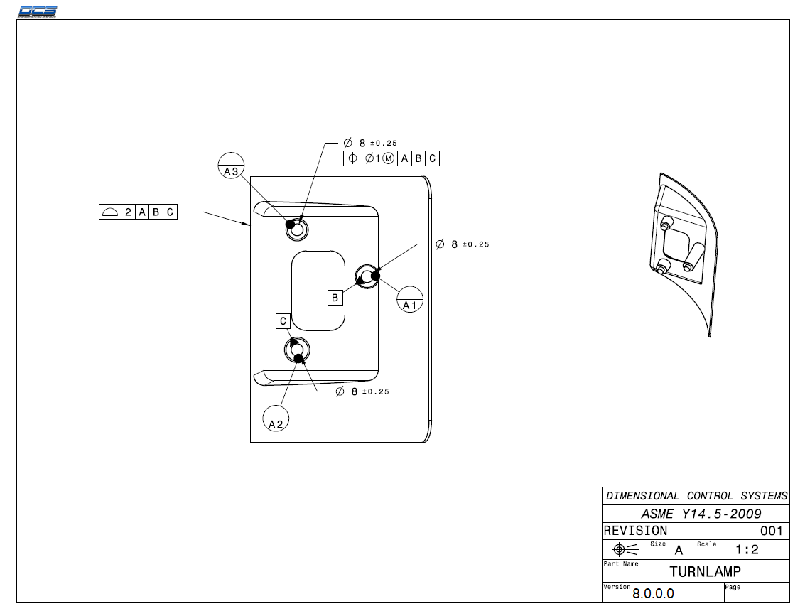
Note that the locators are the datum features for the part. This is generally a good datum strategy as it uses the functional features of the part as the datum features and drives the variation to the less critical features. However, this is not always the case. The datum features are not always the locators of the part. When creating models in 3DCS, you must determine which features locate the physical part then define the move in the software to use those features.
First, save the model under a new name to start the lesson.
•With the Analyst_Tutorial_Lesson3 tab open, Go to the North quadrant of the Compass (called My Social and Collaborative Apps) and select the Collaborative Lifecycle app.
•Select the Analyst_Tutorial_Lesson3 Simulation and select ![]() Duplicate from the toolbar at the bottom.
Duplicate from the toolbar at the bottom.
•Right-click on the new duplicated Analyst_Tutorial_Lesson3 Simulation in the model tree and select Properties.
•In the Reference tab of the Properties dialog, change the Title to "Analyst_Tutorial_Lesson4".
•In the Compass, go to the South Quadrant (called My Content and Simulation Apps) and select 3DCS Variation Analyst V6 in the V+R My Simulation Apps section to return to the 3DCS Variation Analyst workbench.
•Go to File ![]() Save Management.
Save Management.
•Select the Lesson3.CATProduct and select [Save As...].
•In the Save As dialog, rename the Product to "Lesson4.CATProduct" and click [Save].
•In the Save Management dialog select [OK] to save the CATIA Product under its new name. The model is not saved until you click OK.
•Click the ![]() Application Button then select
Application Button then select ![]() Save As.
Save As.
•Change the File Name to "Lesson4.wtx".
•Click [Save] in the Save As dialog.
•Go to File ![]() Save As.
Save As.
•In the Save a Copy dialog, enter "Lamp_SubAsm_Lesson4" for the File Name, make sure the Type is set to Assembly (*.asm), then click [OK].
•In the Assembly Save a Copy dialog, click [Save Copy and Open] to save the assembly under its new name, and open the newly saved assembly.
•Close the 3DCS Model Navigator and Creo window for Lamp_SubAsm_Lesson3.
•Click ![]() Update Model.
Update Model.
•Go to File ![]() Save As.
Save As.
•In the Save As dialog, enter "Lamp_SubAsm_Lesson4" as the new File name and make sure the type is set to Part Files (*.prt).
•Click [OK] in the Save As dialog.
•Click ![]() Update Model.
Update Model.
•Go to File → Save As.
•In the Save as dialog, enter "Lamp_SubAsm_Lesson4" for the File Name, and make sure the Type is set to Assembly.
•Select [Save] in the Save As dialog.
•Click ![]() Update Model.
Update Model.
Next, we will create the Move for the Turnlamp to the Bracket. Since the Move should be at one level in the tree above the Turnlamp and Bracket, the parent component should be the Lamp_SubAsmLamp_SubAsm_Lesson4.
•Click the ![]() Moves button from the toolbar then select the Lamp_SubAsmLamp_SubAsm_Lesson4 from the Navigation TreeNavigation window3DCS Model Navigator as the Parent Part.
Moves button from the toolbar then select the Lamp_SubAsmLamp_SubAsm_Lesson4 from the Navigation TreeNavigation window3DCS Model Navigator as the Parent Part.
If a part is already selected, the Moves dialog will open for that part. Make sure that the Moves dialog for the Lamp_SubAsmLamp_SubAsm_Lesson4 appears.
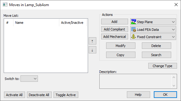
•Select the Step-Plane move from the drop-down list next to [Add].
•Click [Add] to create a new move. The Step-Plane Move dialog will open. It will look like the following picture.
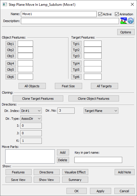
A default name is automatically created for the move. It is important to use informative names and descriptions to help us understand the move later on if we need to come back to it.
•Change the move Name to "Turnlamp-to-Bracket".
•In the Description, type "1st fasten OB hole, 2nd fasten lower IB hole, 3rd fasten upper IB hole.".
The three points on the pin bosses on the Turnlamp are the three primary locators. There are also three corresponding Target points on the Bracket. The three primary locators can be added to the move in any order but we will pick them in number order for simplicity.
•Select [Obj1] to bring up the Pick Feature dialog.
•Select point O_TurnLp_X1 on the Turnlamp.
•Select [Tgt1] to bring back up the Pick Feature dialog.
•Select point T_TurnLp_X1 on the Bracket.
•Repeat this process to select O_TurnLp_X2 and O_TurnLp_X3 for Object points two and three and T_TurnLp_X2 and T_TurnLp_X3 for Target points two and three.
The three primary points are controlling the x direction as shown in the image below.
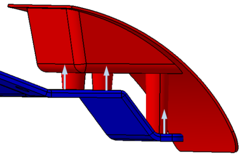
The Turnlamp now has three DoF controlled with "planar" contact in the x direction, controlling TX (translation), RY (rotation), and RZ. However, there remains two translations (TY, TZ) and one rotation (RX) to control. The Turnlamp is controlled in those DoF by pin-hole pairs so we will now input those into our Move. First we will determine which pin-hole pairs are doing the locating. The image below shows the pin diameter and hole diameter for the three pairs.
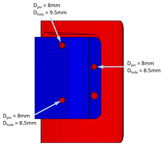
The three pins are all 8mm in diameter but there are two 8.5mm holes and one 9.5mm hole, so it is to the design intent that we will ignore the the 9.5mm hole (the clearance hole) when selecting the locating feature for the Turnlamp Move.
For Object-Target pairs four and five, the Step-Plane Move is looking for two point-point pairs that control the same direction, so we will start off selecting each of the tighter pin-hole pairs once.
•Select [Obj4] and then select the outboard (OB) pin center point O_TurnLp_YZ_Pt in the Turnlamp.
•Select [Tgt4] and then select the corresponding hole center point T_TurnLp_YZ_Pt in the Bracket.
•Repeat this process to add O_TurnLp_Y_Pt and T_TurnLp_Y_Pt to their respective lists.
With those two pairs selected as four and five, we are setting 3DCS up to control the Turnlamp in the direction specified below, as if the two pin-hole pairs compose a "line" in a plane-line-point 3-2-1 locating scheme.
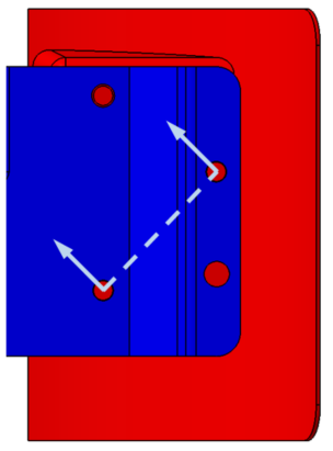
These two translational controls combine to control two additional DoF, but we still have one DoF free. Remember, each point we select is only controlling one DoF, so despite the fact that we are selecting a pin-hole pair, if it only appears in our list once, it is only controlling one DoF and therefore acting more like a slot than a hole. Before selecting our sixth and final pair of points, our Turnlamp is still able to translate along the direction shown below.
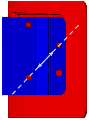
To control this final DoF, we will return to the outboard (OB) pin-hole pair that we used for Obj4 and Tgt4. This will give the pin-hole pair a second DoF of control making it behave like we would expect a pin-hole pair to behave, with two orthogonal directions of control.
•Select [Obj6] and then select the outboard (OB) pin center point O_TurnLp_YZ_Pt in the Turnlamp.
•Select [Tgt6] and then select the corresponding hole center point T_TurnLp_YZ_Pt in the Bracket.
The top half of the Step Plane Move dialog should now look like the following image.
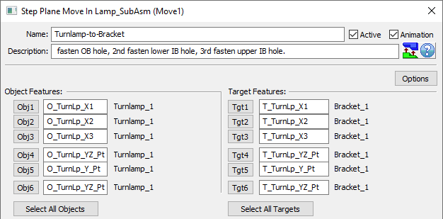
Obj4 and Obj6 must be the same pin, the OB pin. Because it locates the Turnlamp in two directions, the OB pin feature must be added to the move twice. The first time it is added, the OB pin controls the secondary direction. The second time it is added, it controls the tertiary direction. Obj5, the lower IB pin, works in tandem with Obj4 to control the secondary direction.
Consequently, because the Lower IB pin only appears as Obj5, it means that it only controls one direction in the Step-Plane Move and, despite that it is in fact a pin-hole pair, 3DCS is treating it as a pin-slot pair because it only has one DoF of control. Granting this second pin with two DoF of control would in fact be over-constraining the model, we cannot have the OB pin and lower IB pin both controlling the final tertiary direction. Later we will address a refinement we can add to this Step-Plane Move that will better simulate this locating scheme.
The next step is to validate/define the move's directions. Directions are always converted to a unit vector, i.e., the length of the vector is 1. Vectors are represented with I, J, and K as component directions in X, Y, and Z respectively. In Moves, a plane is define by a direction and a point. The plane is through the point and normal to the direction.
For the Step-Plane Move, there are three directions to define. The first direction, Dir#1, defines the direction of the primary planes. Therefore, the direction should be normal to the Bracket surface (in the X direction). A direction and its opposite direction (for example: the +x direction and -x direction) will be equivalent in a move.
•Set the Dir. Index to Dir#1 and verify its Dir. Type is set to AssocDir. Verify that the direction is (-1,0,0).
The second direction, Dir#2, defines the direction of the secondary planes. The direction should be perpendicular to the primary direction and to the line between the two locating pins (the two pins will both locate the part in this direction).
•Set the Dir. Index to Dir#2 and verify its Dir. Type is Auto. 3DCS will automatically calculate the direction.

The third direction, Dir#3, defines the direction of the tertiary plane. The direction should be parallel to the line between the two locating pins (only one of the pins will locate the part in this direction).
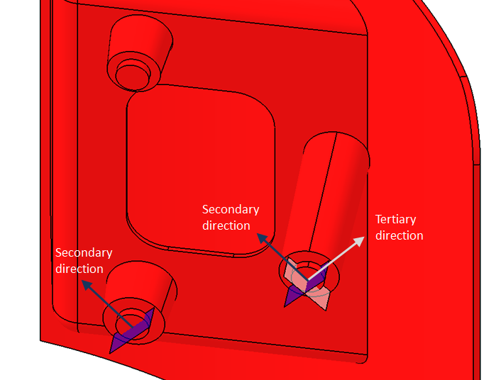
•Set the Dir. Index to Dir#3 and verify its Dir. Type is Auto. 3DCS will automatically calculate the direction. Verify the directions are similar to the ones shown in the following graphic.

As mentioned above, only one of the Bracket holes, the "4-way" hole, locates the Turnlamp in all directions. The second, "2-way" hole does not locate the Turnlamp in the Tertiary direction. Therefore, the hole is assumed to be slotted or large enough in one direction to accommodate all the part variation. Otherwise, the hole and pin would interfere ("wink,") and the Turnlamp could not be assembled. Furthermore, the third hole does not locate at all, i.e. it is a clearance hole, and could interfere in any direction. 3DCS does not automatically check for this condition. Measures can be made, however, to prove no interference is occurring. These assumptions will be tested in a later lesson.
Finally, we must specify which part we want to move. When adding Object Features, the Move Parts field will automatically be filled based on the object part and the move's parent's location in the Navigation Tree. We must ensure, however, that the correct part is selected. The Move Parts should only include the Turnlamp.
•Verify the Move Parts field contains only the Turnlamp as shown in the following picture.

Below Move Parts, there are two buttons to show the different aspects of the move. These help you to verify that your move was created properly.

[Features] will show which features are being used in the move. Object Features will show up with a O1, O2, etc. label next to them. Target Features will show up with a T1, T2, etc. label next to them.
[Directions] will show arrows for the directions defining the planes. For a Step-Plane Move, three different directions are shown.
•Click [Features] to see the features used in the move. Verify that O1 aligns with T1, O2 with T2, etc.
•Click [Close].
•Click [Directions] to see the directions used in the move. Verify that the arrows are showing the correct directions for the planes. They should match the images below (Note: your model may be in the exploded position and therefore the arrows will only show up on the Bracket).

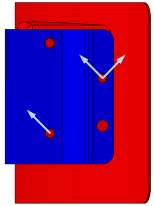
•Click [Close].
•Click [OK] to close the Step Plane Move dialog.
Note: [OK] will save any changes made in the dialog and close the dialog. [Apply] will save any changes made and keep the dialog open.
•Click [OK] to close the Moves dialog
It is important to validate any move you create. One way to validate a move is by assembling the parts. The parts should move into their correct positions. If they do not, then a move may have an error. Once we have tolerances, we will be able to fully validate that a move was created correctly.
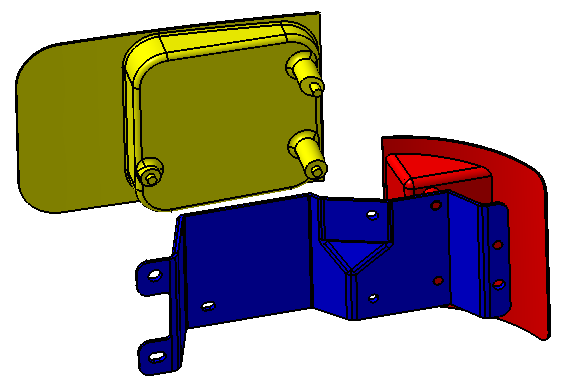
•Click the ![]() Nominal Build button to apply the Moves. Verify that the Turnlamp moves to the Bracket correctly. The Headlamp should not move. The parts should look like the image below.
Nominal Build button to apply the Moves. Verify that the Turnlamp moves to the Bracket correctly. The Headlamp should not move. The parts should look like the image below.
•Click ![]() Separate.
Separate.
•Save the model.