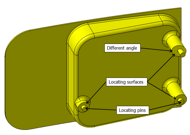
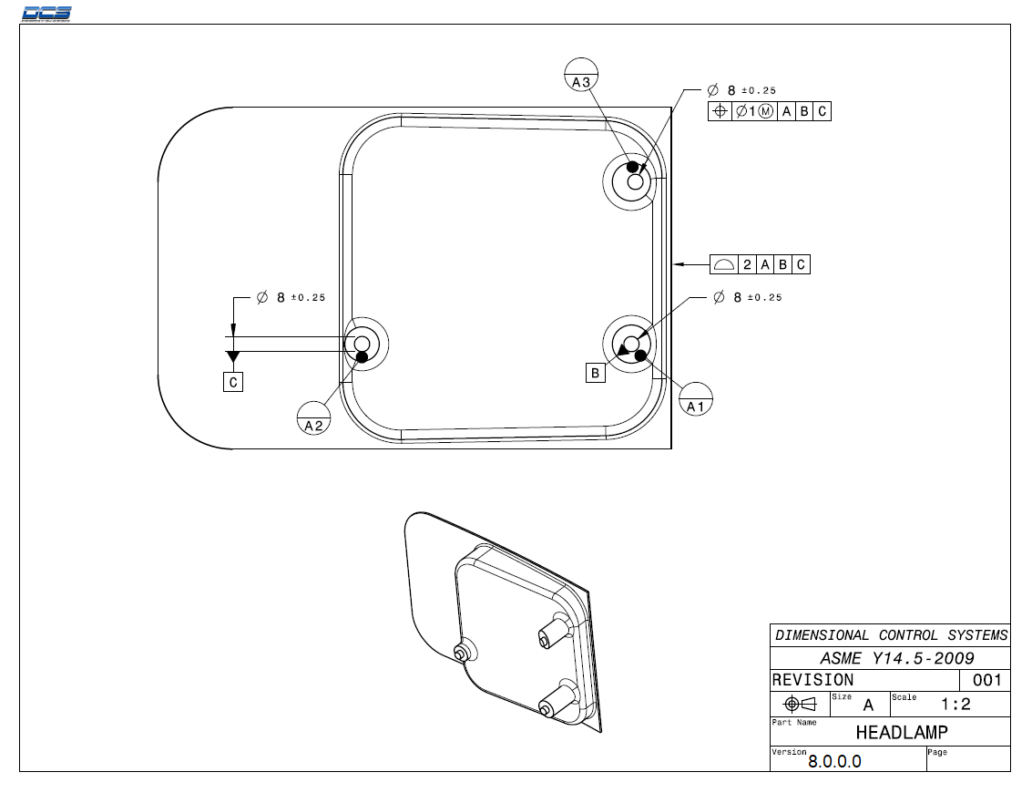
Now, we will walk through moving the Headlamp to the Bracket. Similar to the Turnlamp, the Headlamp will be located using three surfaces and two pins. Because one of the surfaces is at a different angle from the other two, we need to use the Six-Plane Move, which, unlike the Step-Plane Move, allows us to have slightly different directions for the first three Object-Target pairs. The pins will control the secondary and tertiary directions. Like before on the Turnlamp, the Headlamp locators are the datum features for the part.
•Click the ![]() Moves button from the toolbar then select the Lamp_SubAsmLamp_SubAsm_Lesson4 in the tree as the Parent Part.
Moves button from the toolbar then select the Lamp_SubAsmLamp_SubAsm_Lesson4 in the tree as the Parent Part.
•Select Six-Plane from the drop-down list next to [Add].
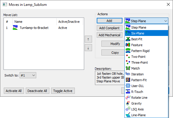
•Click [Add] to create a new move. The Six-Plane Move dialog will open. It will look like the following picture.
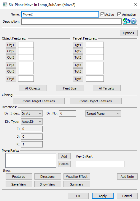
•Change the move Name to "Headlamp-to-Bracket".
•In the Description, type "1st fasten lower OB hole, 2nd fasten IB slot, 3rd fasten upper IB hole."
This time, instead of having two tight holes doing the locating for the Object part, we have a single tight hole as well a slot. We will use the same process that we used for the Turnlamp, however because we've already gone through the process in detail once we can use the [All Objects] and [All Targets] buttons to accelerate the creation of this Move. The three points on the pin bosses on the Headlamp are the three primary locators. Then the two pins that go into the tighter hole and the slot will act as our secondary and tertiary locators.
•Click [All Objects].
•Select point O_HeadLp_X1 on the Headlamp.
•Select point O_HeadLp_X2 on the Headlamp.
•Select point O_HeadLp_X3 on the Headlamp.
•Select point O_HeadLp_YZ_Pt on the Headlamp.
•Select point O_HeadLp_Z_Pt on the Headlamp.
•Return to point O_HeadLp_YZ_Pt on the Headlamp for the final Object Feature.
After selecting the sixth object, the Six-Plane Move dialog will reopen.
Next, the Bracket features will be selected as Target Features for the Headlamp Move. The order of Target Features should match the order of the Object Features so that the object part moves correctly to the target.
•Click [All Targets].
•Select point T_HeadLp_X1 on the Bracket.
•Select point T_HeadLp_X2 on the Bracket.
•Select point T_HeadLp_X3 on the Bracket.
•Select point T_HeadLp_YZ_Pt on the Bracket.
•Select slot T_HeadLp_Z on the Bracket. This is in the Features section of the tree rather than the Points section where all prior selections have been.
•Return to point T_HeadLp_YZ_Pt on the Bracket for the final Object Feature.
After selecting the sixth target, the Six-Plane Move dialog will reopen. The Dialog should look like the image below. Your CadSurf numbers may be different.
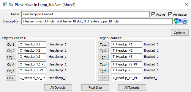
Next, we will define the directions. Unlike the Step-Plane Move for the Turnlamp, where multiple points used the same direction, each pair of points will have their own direction in the Six-Plane Move. Obj1 and Tgt1 are controlled by Dir#1, Obj2 and Tgt2 are controlled by Dir#2, Obj3 and Tgt3 are controlled by Dir#3, and so on. The Six-Plane Move still follows the 3-2-1 locating scheme so Dir#1, Dir#2, and Dir#3 control the primary plane; Dir#4 and Dir#5 control the secondary plane; and Dir#6 controls the tertiary plane.
•Set the Dir. Index to Dir#1 and verify the Dir. Type is set to AssocDir. Verify that the direction is (-1, 0, 0).
•Set the Dir. Index to Dir#2 and verify the Dir. Type is set to AssocDir. Verify that the direction is (-1, 0, 0).
•Set the Dir. Index to Dir#3 and verify the Dir. Type is set to AssocDir. Verify that the direction is (-0.94, 0.34, 0).
•Set the Dir. Index to Dir#4 and verify the Dir. Type is set to Auto. Verify that the direction is (0, 0, 1).
•Set the Dir. Index to Dir#5 and verify the Dir. Type is set to Auto. Verify that the direction is (0, 0, 1).
•Set the Dir. Index to Dir#6 and notice the Dir. Type is set to Auto by default.
With Dir#6 set to Auto, we get (0.12, 0.99, 0) for the direction. For faces we want the direction to be normal to that surface and for holes/pins we want the direction to be normal to the axis. This direction is calculated from the position of the hole and slot in the geometry of the Bracket (the hole and slot are not in the same YZ plane). The axis of the hole in the Bracket is in the X direction, so the pin and hole features for Obj6 and Tgt6 have should no control in the X-direction so we need to manually set the direction using Type In.
•Set the Dir. Type to Type In for Dir#6. Enter (0, 1, 0) for the direction.
The six directions should be similar to the image below.

Finally, you must define which part you want to move. When adding Object Features, the Move Parts field will automatically be filled. You must ensure, however, that it is filled correctly. This move should only move the Headlamp.
•Verify the Move Parts field contains only the Headlamp as shown in the following picture.

Again, it is good practice to show the features and directions of a move to verify that they are correct.
•Click [Features] to see the features used in the move.
•Click [Close].
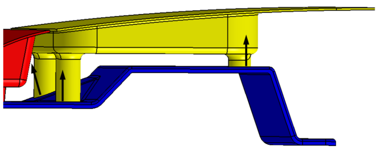
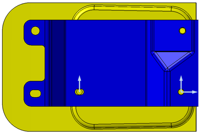
•Click [Directions] to see the directions used in the move. They should match the images below (Note: your model may be in the exploded position and therefore the arrows will only show up on the Bracket).
•Click [Close].
•Click [OK] in the Six-Plane Move dialog to save the move and close the dialog.
•Click [OK] in the Moves dialog.
Verify the Headlamp-to-Bracket Move was created correctly by assembling the parts.
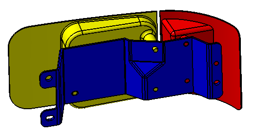
•Click the ![]() Nominal Build button and verify that both the Turnlamp and Headlamp move to the Bracket correctly. The parts should look like the image below.
Nominal Build button and verify that both the Turnlamp and Headlamp move to the Bracket correctly. The parts should look like the image below.
•Click ![]() Separate.
Separate.
You can also validate the moves by animating the build sequence.
•Click ![]() Animate. This opens the Animation dialog.
Animate. This opens the Animation dialog.
•Click on ![]() Forward One Assembly to animate the Turnlamp move.
Forward One Assembly to animate the Turnlamp move.
•Click on ![]() Forward One Assembly again to animate the Headlamp move.
Forward One Assembly again to animate the Headlamp move.
The Turnlamp and Headlamp should end up in the correct position on the Bracket.
•Click the [X][OK] to close the Animate dialog.
•Click ![]() Separate.
Separate.
•Save the model.