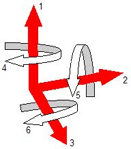
In this lesson, you will learn how to create moves for locating the Headlamp and Turnlamp to the Bracket. Most moves represent the attachment of one part (or assembly) to another. In 3DCS, the part that is being attached is referred to as the "object" part. The part that is being attached to is referred to as the "target" part. Multiple components can make up the object or target in a single Move. This attachment constrains the object part's Degrees of Freedom (DoF). A part has six DoF: three translational and three rotational.

A part is fully constrained if all six DoF are controlled. If a part has less than six DoF controlled, it is only partially constrained. This results in movement after attachment, such as in a hinge assembly. A hinge joint typically can still rotate in one direction, so it has one DoF free. If a part has more than six DoF controlled, it is over-constrained . This results in bending or deformation of the part. This tutorial only deals with rigid parts that are fully constrained. However, kinematics and bending are powerful tools and are covered in advanced training.
The features used to attach the parts are known as locators. Locators can be on a part or in a fixture. The locators can be represented in a model with points or features. Variation of the locators stack up from the piece part level through the Moves to the final product level. Because of variation, the object locator points will not always be coincident with the target locator points. To account for this, 3DCS locates points to planes. The planes are defined by a point and a direction.
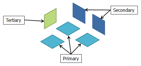
In order to model the many different ways that parts can be attached to each other, 3DCS contains many different Move routines for constraining a part's DoF. The most common type of Move will constrain the object part by aligning six points to six planes. Three of the planes must have approximately the same direction and the points must not be in a straight line. These planes are referred to as the "primary planes" and together they control three DoF: one translation and two rotation. The next two planes must have approximately the same direction to each other and be approximately perpendicular to the primary planes. These two planes are referred to as the "secondary planes" and they control two more DoF: one translation and one rotation. The last plane must be approximately perpendicular to the primary and secondary planes. This plane is referred to as the "tertiary plane" and it controls one DoF: the final translation. This type of Move is referred to as a 3-2-1 locating scheme.

In 3DCS, the Step Plane and Six-Plane Move types follow the 3-2-1 locating scheme. You will use the Step Plane Move to locate the Turnlamp to the Bracket and the Six-Plane Move to locate the Headlamp to the Bracket. The Step Plane Move requires the three primary planes to have the same normal direction. Similarly, the Step Plane Move requires the two secondary planes to have the same normal direction (while still being approximately perpendicular to the primary direction). The Six-Plane Move allows for the primary planes to have different individual directions to control the same general primary direction such as with a curved surface. Likewise, the Six-Plane Move allows for the secondary planes to have different individual directions to control the same general secondary direction. This means a Six-Plane Move can cover more Move cases than the Step Plane Move but the Six-Plane Move requires more input directions than the Step Plane Move.
Although these Moves are based on points, features may also be selected directly in the Move dialog. Every feature has a Feature Locator Point associated with it. This point is internally defined by 3DCS as the average of all of the nodes of the surface, usually located around the middle of the feature. When features are selected in a point-based Move, the Move will be executed as though a point at the Feature Locator Point has been picked.
Moves should always be placed in the tree at least one level above the parts being used in the Move. If the Move is at a lower level, the Move will not be able to refer to both the object and target locator tolerances and will incorrectly result in less variation at the assembly level. In 3DCS, parts maintain their relative position after a Move. If a part is moved multiple times, the last Move will overwrite the location established by the earlier Moves, so the Move sequence is important. The Move sequence of your model should match the assembly order of your product. The order of Moves within a parent will set the Move sequence.