The
|
File Version supported with DCS Converter (14.10.000/8.2.0.0) |
||
CAD Software |
Version |
DCS License |
ACIS |
2018 1.0 (R1 to R28) |
TM_Powerpack |
AutoCAD |
R9-2022 |
TM_Powerpack |
CATIA V4 |
Read: 4.2.4. Write: 4.1.9 to 4.2.4 |
TM_Powerpack |
CATIA V5 (V6) CGR |
R20 - V5-6R2023 (R33) |
TM_Powerpack |
3DEXPERIENCE/3DXML |
Up to R2023x 4.0 to 4.3 |
TM_Powerpack |
DXF/DWG |
Up to 2021 |
TM_Powerpack |
HSF |
Up to 22.0 |
TM_Powerpack |
UG/NX |
Read: NX12.0, NX CR 2212 |
TM_Powerpack |
JT |
Up to 10.8 |
TM_JT |
Inventor |
Up to 2019 |
TM_Powerpack |
NGRAIN |
Write: 3.2; 4.0; 4.1; 5.1 |
TM_Powerpack |
Parasolid |
Up to 30.0 |
TM_Powerpack |
Pro/E |
Read: Wildfire 5.0 |
TM_Powerpack |
SolidEdge |
Read: 2024 |
TM_Powerpack |
SOLIDWORKS |
1997 to 2023 |
TM_Powerpack |
IGES |
4.0; 4.2; 5.2; 5.3 |
TM_Basic |
STEP |
AP203, AP214, AP242 |
TM_Basic |
VRML |
1.0 to 2.0 |
TM_Basic |
MENUS
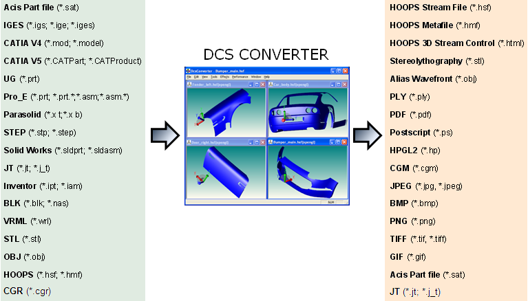
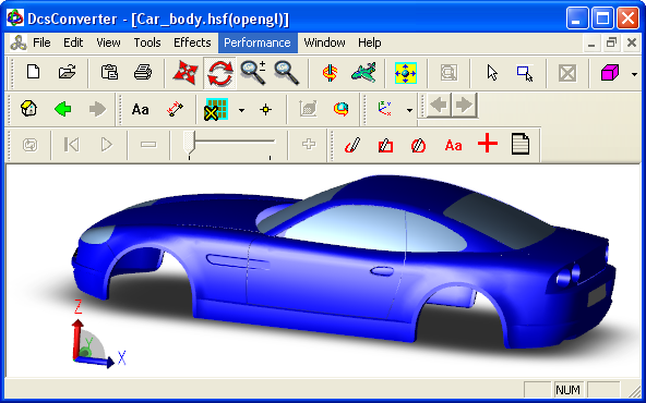
![]() DCS Converter is found under the Geometry tab. The DCS Converter window displays the following menus:
DCS Converter is found under the Geometry tab. The DCS Converter window displays the following menus:
File menu
•New (Ctrl+N) - Creates a New editing window.
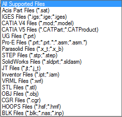
•Open (Ctrl+O) - Opens an existing CAD File. The following CAD files can be opened:
•Import - Imports one or more existing CAD File into the current window. Allows importing the file types listed under the Open menu.
•Load (Ctrl+L) - Replaces the contents of the current window with an existing CAD File.
•Batch Conversion - Allows conversion of multiple CAD files of the same type to .hsf format. Opens the file types listed under the Open menu.
•Close - Closes the active window.
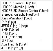
•Save As - Prompts the user to Save the CAD file in the active window. The available file formats are shown in the picture, below:
•Save Bodies As - Prompts the user to Save the CAD Assembly file in the active window as multiple .hsf files.
•Print (Ctrl+P) - Prints the content of the entire active window of the 3DCS Converter.
•Print Preview - Print Preview function allows the user to preview the contents and layout of the active window before it is printed.
•Print Setup... - Sets up the orientation and paper size for printing and defines the printer that the file will print to.
•Exit - Exits the SAT Editor
Edit menu
•Create - Creates new geometry in the current window.
![]() Block - Opens the Create Object function to generate a block by entering size and coordinates.
Block - Opens the Create Object function to generate a block by entering size and coordinates.
![]() Cylinder - Opens the Create Object function to generate a cylinder by entering size and coordinates.
Cylinder - Opens the Create Object function to generate a cylinder by entering size and coordinates.
![]() Sphere - Opens the Create Object function to generate a sphere by entering size and coordinates.
Sphere - Opens the Create Object function to generate a sphere by entering size and coordinates.
![]() Torus - Opens the Create Object function to generate a Torus by entering size and coordinates.
Torus - Opens the Create Object function to generate a Torus by entering size and coordinates.
![]() Prism - Opens the Create Object function to generate a prism by entering size and coordinates.
Prism - Opens the Create Object function to generate a prism by entering size and coordinates.
![]() Plane - Opens the Create Object function to generate a plane by entering size and coordinates.
Plane - Opens the Create Object function to generate a plane by entering size and coordinates.
![]() Cylinder Face - Opens the Create Object function to generate the lateral surface of a cylinder by entering size and coordinates.
Cylinder Face - Opens the Create Object function to generate the lateral surface of a cylinder by entering size and coordinates.
![]() Sphere Face - Opens the Create Object function to generate a half of a sphere by entering size and coordinates.
Sphere Face - Opens the Create Object function to generate a half of a sphere by entering size and coordinates.
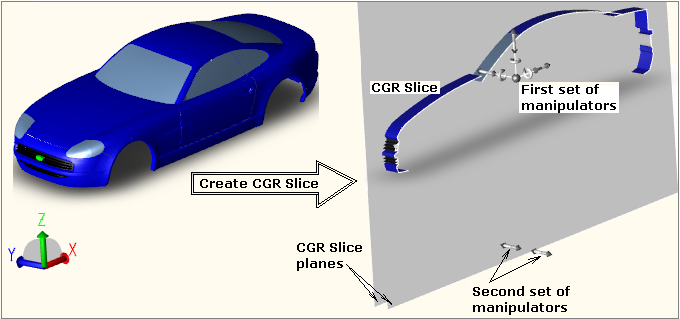
![]() Create CGR Slice - Will create two parallel cutting planes and display only the geometry located between the two planes. The planes can be translated or rotated using the first set of manipulators. To modify the width of the slice, use the second set of manipulators.
Create CGR Slice - Will create two parallel cutting planes and display only the geometry located between the two planes. The planes can be translated or rotated using the first set of manipulators. To modify the width of the slice, use the second set of manipulators.
![]() Markup - Allows for annotation of a 2D drawing.
Markup - Allows for annotation of a 2D drawing.
![]() Freehand - Draws free style curves.
Freehand - Draws free style curves.
![]() Circle - Draws circles.
Circle - Draws circles.
![]() Rectangle - Draws rectangles.
Rectangle - Draws rectangles.
![]() Note - Allows text to be placed at a desired screen location.
Note - Allows text to be placed at a desired screen location.
•Selection - Allows for selection and deletion of entities in the current window.
![]() Select by Single Click - Allows for entities to be selected one at a time. To select more than one entity, hold down the Shift or Ctrl Key while selecting.
Select by Single Click - Allows for entities to be selected one at a time. To select more than one entity, hold down the Shift or Ctrl Key while selecting.
![]() Select by Window - Allows for entities to be selected with a window.
Select by Window - Allows for entities to be selected with a window.
![]() Select by Polygon - Selects and highlights all the specified geometry types within a user specified polygon.
Select by Polygon - Selects and highlights all the specified geometry types within a user specified polygon.
![]() Select By PolyLine - Selects and highlights all the specified geometry types that intersect a user define polyline.
Select By PolyLine - Selects and highlights all the specified geometry types that intersect a user define polyline.
![]() Delete Selection - Deletes the current selection.
Delete Selection - Deletes the current selection.
![]() Delete Unselected - Deletes the unselected entities.
Delete Unselected - Deletes the unselected entities.
![]() Zoom To Selection - Zooms to the currently selected object (select an item first, only then will this toolbar button will be activated)
Zoom To Selection - Zooms to the currently selected object (select an item first, only then will this toolbar button will be activated)
![]() Translate Selection - Allows manipulation (translation only) of the current selection.
Translate Selection - Allows manipulation (translation only) of the current selection.
![]() Reverse Selections - Selects those features that are not currently selected and unselects those that are selected.
Reverse Selections - Selects those features that are not currently selected and unselects those that are selected.
•Combine All & Heal - Recommended for models that seem to be displayed incorrectly.
Note: This function is not required if Tools / AutoHeal is active.
•Reverse Normals - Replaces the selected objects with their solid "opposite". This will reverse the directions of the selected surfaces.
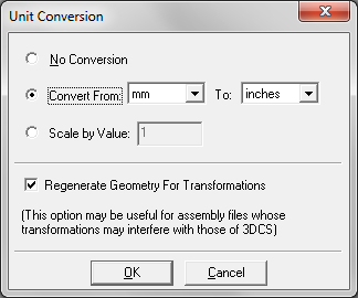
•Scale Model for Units... - Allows for CAD Files to be scaled.
Sometimes an exporting application can inadvertently write out a model scale larger or smaller than what the part was designed in. This results in a part being translated into DCS Converter very large or very small. For example a part designed in mm that was 100 mm long and written out to Meters would come into DCS Converter as 100 Meters long! In this case applying a scaling factor of .001 would bring the part back down to mm.
Procedure: After first selecting a part or multiple parts, click the Scale Model for Units to apply a scaling factor to the part(s). In the Unit Conversion dialog, add a check-mark for Regenerate Geometry For Transformations, then click OK.
•Entity Color... - Allows changing the color of the selected entity.
•Copy - Places an image of the active window on the Windows Clipboard.
View menu
Allows for various graphic display options.
•Autoscale (Ctrl+A) - Fits the objects to the view window.
•Set View
![]() Mouse Manipulation - Allows repositioning and rotating the object.
Mouse Manipulation - Allows repositioning and rotating the object.
![]() Pan - Allows repositioning (translation relative to the view window) of the object.
Pan - Allows repositioning (translation relative to the view window) of the object.
![]() Rotate - Allows rotating the object about its geometric center.
Rotate - Allows rotating the object about its geometric center.
![]() Zoom - Zooms in and out on the part.
Zoom - Zooms in and out on the part.
![]() Zoom To Window - Zooms in on a selection window.
Zoom To Window - Zooms in on a selection window.
![]() Render Mode - Allows for different ways to display the parts.
Render Mode - Allows for different ways to display the parts.
![]() Triangulated - Divides the object surface into triangles.
Triangulated - Divides the object surface into triangles.
![]() Wireframe - Shows the wireframe of the object.
Wireframe - Shows the wireframe of the object.
![]() Shaded - Shows the object shaded.
Shaded - Shows the object shaded.
![]() Hidden Line - Shows the object in wireframe with hidden lines removed.
Hidden Line - Shows the object in wireframe with hidden lines removed.
•Coordinate System - Switches between Left Handed and Right Handed Coordinate System.
![]() Left Handed - Orients the objects to the Left Handed Coordinate System.
Left Handed - Orients the objects to the Left Handed Coordinate System.
![]() Right Handed - Orients the objects to the Right Handed Coordinate System.
Right Handed - Orients the objects to the Right Handed Coordinate System.
•Backplane Culling - Allows for shadowing of the part on a backplane in the graphics window.
•Cross Section - Sections the part with a y-direction oriented plane through the middle of the part
•Visibility - Changes the way an object is visualized.
![]() Edges - Shows/hides edges of the objects.
Edges - Shows/hides edges of the objects.
![]() Faces - Shows/hides faces of the objects.
Faces - Shows/hides faces of the objects.
![]() Lights - Turns on/off the lights that fall on the parts.
Lights - Turns on/off the lights that fall on the parts.
•Projection - Allows choosing between types of projection for viewing the parts.
![]() Orthographic - Shows an orthogonal projection view of the object.
Orthographic - Shows an orthogonal projection view of the object.
![]() Perspective - Shows the perspective projection view of the object.
Perspective - Shows the perspective projection view of the object.
•Polygon Handedness - Selects the part meshing to be defined either clockwise or counterclockwise (affects mesh shading and surface normal direction)
![]() Right - Sets handedness to right (counterclockwise)
Right - Sets handedness to right (counterclockwise)
![]() Left - Sets handedness to left (clockwise)
Left - Sets handedness to left (clockwise)
![]() None - Turns off handedness (no influence to mesh shading or surface normal direction)
None - Turns off handedness (no influence to mesh shading or surface normal direction)
•Smooth Transition - Translates and rotates the object to match the isometric position and shows the transition between its initial and final position. If not checked, the object is shown only in the final position.
•Frame Rate Options... - Opens Detail Properties dialog box where the Frame Rate Settings and Lod Settings can be adjusted.
•LOD Level - Level Of Detail setting
![]() Original - Lowest level of detail
Original - Lowest level of detail
![]() Level 1 - Medium level of detail
Level 1 - Medium level of detail
![]() Level 2 - Highest level of detail
Level 2 - Highest level of detail
•Tile - Displays the windows in a tiled arrangement.
•Toolbar - Allows turning on or off each of the four toolbars: Standard, Tools, Mark-Up Text, Standard Views, Animation, CAE, CMM, Point Cloud.
•Status Bar - Will display the 3DCS Converter Status Bar, when checked.
Tools menu
Allows for various graphic inquire functions and options.
•Test Performance - Rotates the object 360 degrees and shows model information such as segments, shells, triangles and vertices in the DCSConverter dialog box.
•Query Model - Lists information about an object (geometry type, number of vertices, etc.).
•Measure Distance - Measures a distance with a click and drag in the graphics window.
| Note: | DcsConverter always has an active mode, for example, when in Tools/Query Model or Tools/Measure Distance mode, select Pan or Rotate to get off of those modes and into the Pan or Rotate mode. |
•Segment Browser - This tool allows the user to explore the segments and attributes of the file they are viewing.
Note: The Segment Browser can be opened directly in the 3DCS model using Ctrl+Alt+Shift+Q short-cut key.
•Keyframe Editor - Is provided as a simple tool to create animations from existing geometry. It is a tool used to quickly enhance graph data with animations.
•Material Properties... - See Material Editor
•Material Selector - Material Selector allows you to drag styles onto parts. Create some styles in the Material Properties dialog, close out, and then start the Material Selector. You then can drag & drop styles onto parts.
•LOD Generation - Level-of-Detail (LOD) is an essential element of large model visualization. It involves simplifying objects that have faceted representations so that they will be drawn using a smaller number of triangles. As a result, LOD can improve performance by an order of magnitude while maintaining the visual integrity of the model.
•Clash Browser (or Collision Browser) - allows the user to detect intersection between geometry in the model.
•Auto Heal - Turns on/off the Auto Heal feature when opening files.
•Embed Solid Data in Hsf - Allows for saving an .hsf file with added solid body information.
•Merge Faces - Instructs to merge all the shells that were generated to represent a BODY (one shell for each FACE) into a single shell. In the case of a multi-colored BODY, the shells corresponding to FACES that have the same color attribute will be merged into one shell, resulting in, as many shells are there are distinct colors in the BODY entity.
•Options... - Opens the dcsConverter Options dialog for changing the default settings.
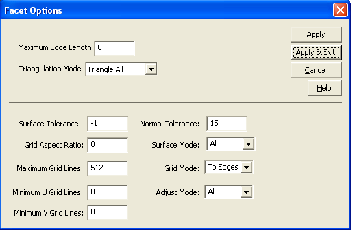
Facet Options: opens a dialog box with the following refinement functions:
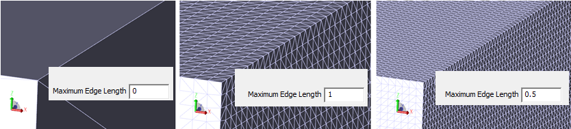
![]() Maximum Edge Length - The edge length is the length of a facet edge. The maximum edge length value allows the facet edge length to be within the specified limit. This is the only way to subdivide facets further in planer faces.
Maximum Edge Length - The edge length is the length of a facet edge. The maximum edge length value allows the facet edge length to be within the specified limit. This is the only way to subdivide facets further in planer faces.
The maximum edge length specifies the maximum length of a side of a cell in object space. Since a facet cannot be larger than the cell, this determines the maximum size of the facet. If the value is zero, maximum edge length is not considered in faceting.
Setting the value to 1 will result in a denser mesh then setting it to 10. If you set the value between 0 and 1 will result into an even denser mesh than when using 1.
![]() Triangulation Mode - Specifies the triangulation style. It specifies how much triangulation to perform. The allowable values are:
Triangulation Mode - Specifies the triangulation style. It specifies how much triangulation to perform. The allowable values are:
Triangle None No triangulation.
Triangle All Triangulate all facets
Triangle Fringe 1 Triangulate at the fringe layer.
Triangle Fringe 2 Triangulate two (2) fringe layers - two outermost peripheral grid facets are triangulated.
Triangle Fringe 3 Triangulate three (3) fringe layers.
Triangle Fringe 4 Triangulate four (4) fringe layers.
![]() Surface Tolerance - Specifies the distance between the facet and the part of the surface it is representing, basically the maximum distance between a facet and the true surface. The proper value is dependent on the model size. When the surface tolerance is set to -1, the faceter will use a surface tolerance that is independent of the model size. This is a fraction (e.g., 1/1000th) of the diagonal of the bounding box of the face. This results in faceting that is independent of the units of measurement of the face. For example if the surface tolerance is 0.1, means that every facet is not more than 0.1 unit away from the mathematical spline surface. This results in a smaller but more facets in order to satisfy the surface tolerance constraint.
Surface Tolerance - Specifies the distance between the facet and the part of the surface it is representing, basically the maximum distance between a facet and the true surface. The proper value is dependent on the model size. When the surface tolerance is set to -1, the faceter will use a surface tolerance that is independent of the model size. This is a fraction (e.g., 1/1000th) of the diagonal of the bounding box of the face. This results in faceting that is independent of the units of measurement of the face. For example if the surface tolerance is 0.1, means that every facet is not more than 0.1 unit away from the mathematical spline surface. This results in a smaller but more facets in order to satisfy the surface tolerance constraint.
![]() Grid Aspect Ratio - Specifies the ratio of the u and v lengths of a uv grid cell. Setting the aspect ratio to 1.0 indicates that the grid should be as square as possible.
Grid Aspect Ratio - Specifies the ratio of the u and v lengths of a uv grid cell. Setting the aspect ratio to 1.0 indicates that the grid should be as square as possible.
None Does not subdivide face with a grid.
To Edges Uses a grid and creates intersection points of the grid with the edges.
Interior Uses grid only in the interior. Triangles are generated from the edge to the grid.
![]() Maximum Grid Lines - Specifies the maximum number of grid lines to use.The maximum number of grid lines can prevent the other constraints from being satisfied, so it is recommended to set it to a high value.
Maximum Grid Lines - Specifies the maximum number of grid lines to use.The maximum number of grid lines can prevent the other constraints from being satisfied, so it is recommended to set it to a high value.
![]() Minimum U Grid Lines - Specifies the minimum number of grid lines to use along the u-axis.
Minimum U Grid Lines - Specifies the minimum number of grid lines to use along the u-axis.
![]() Minimum V Grid Lines - Specifies the minimum number of grid lines to use along the v-axis.
Minimum V Grid Lines - Specifies the minimum number of grid lines to use along the v-axis.
![]() Normal Tolerance - Specifies the angle between the surface normals at the two adjacent nodes of a facet. It basically specifies the maximum normal deviation allowed between two normals on a facet. The proper value is usually independent of the model size. A higher normal tolerance (e.g. 25 vs 15) will result in fewer facets, basically a coarser mesh.
Normal Tolerance - Specifies the angle between the surface normals at the two adjacent nodes of a facet. It basically specifies the maximum normal deviation allowed between two normals on a facet. The proper value is usually independent of the model size. A higher normal tolerance (e.g. 25 vs 15) will result in fewer facets, basically a coarser mesh.
![]() Surface Mode - Specifies the type of surface to which the refinement is applicable.
Surface Mode - Specifies the type of surface to which the refinement is applicable.
![]() Grid Mode - Specifies whether a grid is used and whether the points where the grid cuts the edges should be inserted into the edge discretization (converting continuous data into a set of discrete values).
Grid Mode - Specifies whether a grid is used and whether the points where the grid cuts the edges should be inserted into the edge discretization (converting continuous data into a set of discrete values).
![]() Adjust Mode - Specifies the type of adjustment to attempt for triangle smoothing.
Adjust Mode - Specifies the type of adjustment to attempt for triangle smoothing.
![]() Apply - Apply the settings right now.
Apply - Apply the settings right now.
![]() Apply & Exit - Save the settings and exit.
Apply & Exit - Save the settings and exit.
![]() Cancel - Ignore the settings and exit.
Cancel - Ignore the settings and exit.
•IGES Read Options
![]() Use Light Repair - Healing for tolerant modeling using Solid kernel. When checked (default), the Solid entities are healed.
Use Light Repair - Healing for tolerant modeling using Solid kernel. When checked (default), the Solid entities are healed.
![]() Read Attributes - Allows the user to set the value to enable or disable attribute transfer from IGES file to solid file.
Read Attributes - Allows the user to set the value to enable or disable attribute transfer from IGES file to solid file.
•Disable Tristrips - Disables triangle strips, and the triangulation it requires, in shells, and allows quads saving. Incurs a heavy read-time computational cost.
•Light Scaling - The object color is a function of the light falling on that object from each light source. The light from each light source is additive, which can cause a problem if there is more than one light source in a scene.When setting the light scaling, the lights' number, colors, positions, and types (distant, local, or spot) need to be taken into account. Also note that you can purposely set the light scaling too low, which will cause color values greater than 1.0 to be clamped at 1.0. This clamping is not an error; if done excessively, however, it can cause scenes to appear washed out.
•Translator Options - allow the user to modify the settings for the CAD files prior to importing or opening for translation into HSF files in DCS Converter or inside 3DCS.
Effects menu
•None
•Fancy
•Focus on Selection
•Ambient Occlusion - see DCS Converter Options
•Bloom - see DCS Converter Options
•Fast Silhouette Edges - see DCS Converter Options
•Reflection Plane - see DCS Converter Options
•Shadow Maps - see DCS Converter Options
•Simple Shadows - see DCS Converter Options
Performance menu
During a large model visualization, most of the resources on a given system may be dedicated to rendering the details of a model. Thus, when a user tries to examine the model by rotating the camera or zooming in and out, the application may not be able to respond in a timely manner. To improve the performance, the user can select one of the following options:
•Default
•High Performance
•Static Model - see DCS Converter Options
•Segment-Level Display List
•Geometry-Level Display List
•Fixed Framerate - see DCS Converter Options
•Target Framerate - see DCS Converter Options
Window menu
•Cascade - Re-sizes and arranges all open windows in a stacked and staggered fashion.
•Tile Horizontally - Re-sizes and arranges all open windows above each other from top to bottom.
•Tile Vertically - Re-sizes and arranges all open windows next to each other from left to right.
Help
•DCSConverter Log File - Lists error messages that may occur during translation.
•About - Displays information about the software along with available memory.
Note: This program requires the DCS_CONVERTER license from DCS.
TransMagic© is a registered trademark of TransMagic, Inc.
ACIS© and .sat © is a Trademark of Spatial© and Dassault Systemes
Pro/E© is a trademark of Parametric Technology
CATIA© is a registered trademark of Dassault Systemes
Parasolid© is a registered trademark of Electronic Data Systems (EDS)
HOOPS© is a registered trademark of Techsoft America
HSF© is a trademark of OpenHSF.org