All of the options within DCS Converter are now saved in the DCS Config file located: C:\Users\"username"\Application Data\DCS\DCS_SA\config. This link can also be found in the Log file.
General Settings
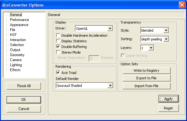
Display
•Driver - Sets the HOOPS display driver: Open GL, WIN GDI, or DX9.
•Disable Hardware Acceleration - If checked, forces HOOPS to use software rendering. Only works for the OpenGL and Direct3D drivers.
•Display Statistics - Displays a small window with basic statistics about which types of geometry were drawn in the last update.
•Double Buffering - The OpenGL Driver supports double-buffering to make animation appear smoother.
•Stereo Mode - If checked and the hardware supports it, stereo viewing will be enabled with the given separation.
Rendering
•Axis Triad - If checked, displays X-Y-Z axis triad at the left-bottom corner of each document.
•Default Render Mode - Sets the start up render mode. Choose from: Brep Hidden Line, Brep Wireframe, Fake Hidden Line, Flat Shaded, Gouraud Shaded, Gouraud Shaded With Lines, Hidden Line, Phong Shaded, Shaded Wireframe, Shaded Vertices, Silhouette, Vertices, Wireframe, Wireframe Silhouette.
Transparency
•Style - Allows you to set the style of transparency.
•Sorting - Allows you to set the sorting algorithm used for transparency.
•Layers - Allows you to set the number of layers for the depth peeling transparency sorting algorithm.
•Depth Writing - Controls whether transparent geometry writes into the z buffer.
Options Set
•Write to Registry - Writes the current options settings to the registry.
•Export to File - Exports the current options settings to a file with the extension .PVO.
•Import from File - Imports a .PVO file that contains a set of options values.
Performance Settings
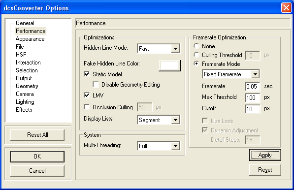
Optimizations
•Hidden Line Mode - Determines how hidden lines are rendered when the hidden line button is selected in the Standard Tool Bar. The options are Fast, Analytic and Fake.
•Fake Hidden Line Color - Determines the color of hidden lines when the fake hidden line mode is enabled.
•Static Model - If checked, HOOPS will generate a parallel optimized segment tree for rendering. When this item is checked, Disable Geometry Editing is enabled and automatically checked as well for optimal performance. If used with display lists turned on, rendering performance could improve significantly.
![]() Disable Geometry Editing - If checked, this prevents geometry editing. This option disables insertion of geometry, translation, rotations, manipulators and any editing in the segment browser.
Disable Geometry Editing - If checked, this prevents geometry editing. This option disables insertion of geometry, translation, rotations, manipulators and any editing in the segment browser.
•LMV (Large Model Visualization) - The ability to generate lower levels of of detail for objects, and maintain a constant framerate by selectively drawing lower detail levels of objects based on their distance from the camera, or whether they lie within the current view. The greatest performance benefits can be seen in a model consisting of numerous 3D objects that are spatially dispersed (engine, aircraft, automobile, power-plant, building, etc...) LMV can also be used with a model containing only a few large 3D objects or maybe only one (these models are common in analysis and oil/gas applications, which need to display very large objects).
•Occlusion Culling - If checked, Occlusion Culling will be performed on the current scene which can result in significant performance gains with some models. This option currently only has effect when the OpenGL driver is selected and certain hardware requirements are met.
•Display Lists - Determines whether display lists will be used. Display lists can be enabled if the Driver is OpenGL or DX9. Display list can be generated at the segment or geometry level.
System
•Multi-Threading - Determines if semaphores are enabled for thread safe activities.
![]() Full - This option renders each 3dGS call completely thread-safe.
Full - This option renders each 3dGS call completely thread-safe.
![]() Basic - Provides basic memory access for read/write locks.
Basic - Provides basic memory access for read/write locks.
![]() Off - Provides no thread protection but also eliminates overhead associated with thread safety.
Off - Provides no thread protection but also eliminates overhead associated with thread safety.
Framerate Optimization
•None - No occlusion culling is performed.
•Culling Threshold - If selected, will set the pixel culling threshold for occlusion culling.
•Framerate Mode - If selected, a framerate mode will determine how much of the scene is rendered at any given time.
![]() Fixed Framerate - The fixed framerate approach is the simplest method for ensuring a good balance between application responsiveness and visual integrity. HOOPS will maintain the exact specified framerate during model manipulation but flashing may occur.
Fixed Framerate - The fixed framerate approach is the simplest method for ensuring a good balance between application responsiveness and visual integrity. HOOPS will maintain the exact specified framerate during model manipulation but flashing may occur.
![]() Target Framerate - For developers who are interested in a smoother non-flickering rendering for very large models, the target framerate approach maybe the best option. HOOPS tries to maintain the framerate during model manipulation. The transition between frames is smooth.
Target Framerate - For developers who are interested in a smoother non-flickering rendering for very large models, the target framerate approach maybe the best option. HOOPS tries to maintain the framerate during model manipulation. The transition between frames is smooth.
![]() Framerate (frames per second) - Target Framerate which is specified in seconds. For instance, 0.1 is equivalent to 10 fps (frames per second).
Framerate (frames per second) - Target Framerate which is specified in seconds. For instance, 0.1 is equivalent to 10 fps (frames per second).
![]() Max Threshold (pixels) - The highest pixel size an object can have for it to be culled from the scene to maintain the framerate.
Max Threshold (pixels) - The highest pixel size an object can have for it to be culled from the scene to maintain the framerate.
![]() Cutoff - The pixel size to trigger culling.
Cutoff - The pixel size to trigger culling.
![]() Use Lods (Level of Detail) - If checked, Level of detail will be used in determining what will be rendered. This option is only available for Target Framerate.
Use Lods (Level of Detail) - If checked, Level of detail will be used in determining what will be rendered. This option is only available for Target Framerate.
![]() Dynamic Adjustment - If checked, culled objects will be "added" back into the scene at the end of manipulation. This option is only available for Target Framerate.
Dynamic Adjustment - If checked, culled objects will be "added" back into the scene at the end of manipulation. This option is only available for Target Framerate.
![]() Detail Steps - Determines the number of buckets that culled objects will be put into for redrawing into the scene. For example, if the Max Threshold is 100 pixels and Details Steps is 5, objects that are between 80 and 100 pixels will be drawn first followed by objects between 60 and 80 pixels and so on.
Detail Steps - Determines the number of buckets that culled objects will be put into for redrawing into the scene. For example, if the Max Threshold is 100 pixels and Details Steps is 5, objects that are between 80 and 100 pixels will be drawn first followed by objects between 60 and 80 pixels and so on.
Appearance Settings
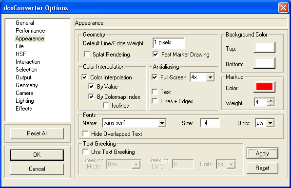
Geometry
•Default Line/Edge Weight - Sets the default line/edge weight.
•Splat Rendering - If checked, point cloud data will be smeared to enhance the appearance.
•Fast Marker Drawing - This method controls whether marker drawing will bias toward performance or quality.
Color Interpolation
•Color Interpolation - If checked, honors the color settings at each vertex of the Shells in the scene and applies a color ramp across the shell.
![]() By Value - Controls the color interpolation scheme for Shells which have vertex level coloring. If checked, the color at each pixel in the face is determined by simply linearly interpolating the RGB color set on the adjacent vertices.
By Value - Controls the color interpolation scheme for Shells which have vertex level coloring. If checked, the color at each pixel in the face is determined by simply linearly interpolating the RGB color set on the adjacent vertices.
![]() By Colormap Index - Controls the color interpolation scheme for Shells which have vertex level coloring. If checked, the color at each pixel by is determined by interpolating between the indices in the colormap. This option is only valid if the Shell vertex colors have been set by Index.
By Colormap Index - Controls the color interpolation scheme for Shells which have vertex level coloring. If checked, the color at each pixel by is determined by interpolating between the indices in the colormap. This option is only valid if the Shell vertex colors have been set by Index.
![]() Isolines - If checked, renders only the Isolines for Shells in the scene which have colors set on their vertices.
Isolines - If checked, renders only the Isolines for Shells in the scene which have colors set on their vertices.
In digital signal processing, anti-aliasing is the technique of minimizing the distortion artifacts known as aliasing when representing a high-resolution signal at a lower resolution (http://en.wikipedia.org/wiki/Anti-aliasing).
•Full Screen - If checked, enables scene anti-aliasing, with the option to set the anti-aliasing quality (number of samples).
•Text - If checked, enables text anti-aliasing.
•Lines + Edges - If checked, enables anti-aliasing for only lines and edges. In practice, this setting is redundant if screen anti-aliasing is already enabled.
Background Color
•Top - Sets the background color for the upper portion of the window. The background color can have a gradient from top to bottom.
•Bottom - Sets the background color for the lower portion of the window. If you prefer a single background color without any gradient, set this color exactly same as the Top Background Color.
Markup
•Color - Sets the color of Markup lines.
•Weight - Sets the line weight (thickness) for the Markup.
Fonts
•Name - Sets the current font for the scene.
•Size - Sets the current font size in points.
•Units - The units specifier can be any of the following:
![]() oru - "Object relative units". The number indicates text size in object space. This allows for fully transformable text, which is sized the same as most of the other geometries.
oru - "Object relative units". The number indicates text size in object space. This allows for fully transformable text, which is sized the same as most of the other geometries.
![]() sru - "Subscreen relative units". The number indicates the fraction of the height of the outermost window (either the subscreen, if any, else the whole screen) that the characters ought to be. The picture is always internally the same, no matter how big the actual screen is. If there is a window manager, as the user changes the window size the characters scale to fit. "0.03 sru" gives a plausible size for menus, for example.
sru - "Subscreen relative units". The number indicates the fraction of the height of the outermost window (either the subscreen, if any, else the whole screen) that the characters ought to be. The picture is always internally the same, no matter how big the actual screen is. If there is a window manager, as the user changes the window size the characters scale to fit. "0.03 sru" gives a plausible size for menus, for example.
![]() wru - "Window relative units". Similar to sru, but the text is measured relative to the local HOOPS window, rather than the outermost window. This is sometimes useful when the user is rescaling internal HOOPS windows on the fly.
wru - "Window relative units". Similar to sru, but the text is measured relative to the local HOOPS window, rather than the outermost window. This is sometimes useful when the user is rescaling internal HOOPS windows on the fly.
![]() pts or points - Points are the units most commonly used by type setters. In HOOPS, a point is equal to 1/72 inch. A 10 point font is a common size for a book, and 12 point fonts are commonly used for reports and on typewriters. Note that "points" are an absolute unit of measurement. If you move onto a different size screen, or onto paper, your geometry and windows will scale but the text, when set in points, will stay the same.
pts or points - Points are the units most commonly used by type setters. In HOOPS, a point is equal to 1/72 inch. A 10 point font is a common size for a book, and 12 point fonts are commonly used for reports and on typewriters. Note that "points" are an absolute unit of measurement. If you move onto a different size screen, or onto paper, your geometry and windows will scale but the text, when set in points, will stay the same.
![]() px or pixels - Many bitmap computer fonts are measured in pixels. If you know exactly the machine you're running on and exactly the font you want, and that font is officially measured in pixels, then px is appropriate to use. Otherwise measuring in pixels might lessen the portability of your program.
px or pixels - Many bitmap computer fonts are measured in pixels. If you know exactly the machine you're running on and exactly the font you want, and that font is officially measured in pixels, then px is appropriate to use. Otherwise measuring in pixels might lessen the portability of your program.
• Hide Overlapped Text - If checked, only text in the foreground will be displayed.
Text Greeking
•Use Text Greeking - Toggles text greeking.
•Greeking Mode - Sets the geometry that will be displayed in place of greeked text.
•Greeking Limit - Sets the distance before text is greeked.
•Units - The units that apply to the greeking limit.
File Settings
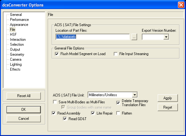
ACIS (.SAT) File Settings
•Location of Part files - The directory location of the HOOPS files.
•Export Version Number - The export version number for HSF files.
General File Options
•Flush Model Segment on Load - If checked, the model segment will be flushed each time a new file is loaded (not opened). Otherwise the file will be loaded into the current model segment.
•File Input Streaming - If checked, as files are loaded you can interact with the model. Note that this option does increase the time it takes to load your scene. If this option is not checked, file loading will be faster but you will not be able to interact with the objects in your scene until the file is completely loaded into the current model segment.
•ACIS (.SAT) File Unit - The unit setting is used for import and export of files in DCS Converter. The default unit is millimeters.
Save Multi-Bodies as Multi-Files: This option will import the CAD Files as multiple parts (one 3DCS part per each CAD feature), individually listed in the Navigation window. If multiple features have the same name, a suffix will be added to each individually created part. This setting allows the user to modify the initial CAD file by hiding or removing some of the newly created parts.
•Delete Temporary Translation Files: The user can keep or delete the temporary SAT files using this option.
•Group bodies with the same name: This option will group the features that have the same name and display them as a single part in the Navigation tree.
Note: If neither Save Multi-Bodies as Multi-Files or Group bodies with the same name option is checked, all imported CAD data will be displayed as a single part in the Navigation window.
•Read Assembly - This option is intended for PDM\PLM integration or other "enterprise style" usage. It will read the assembly structure and part transforms from the CAD file to create a file per part instead of creating a single combined part file.
•Lite Repair - Lite Repair performs the following functions on a part:
1) Repair Initialization. Examines the part and attaches intelligent attributes that are used to establish tolerances for stitching, simplification and Repair.
2) Repair Pre-processing. Find and remove zero-length edges, zero-area faces, and duplicate vertices. These are common, extraneous, & unnecessary geometry.
3) Geometric Simplification. The intelligent attributes established in Repair Initialization are analyzed for the purposes of Geometric Simplification. Geometric Simplification attempts to simplify spline surfaces into analytic surfaces (planes, cylinders, cones, tori, and spheres).
4) Geometric Stitching. The intelligent attributes established in Repair Initialization are analyzed for the purposes of Geometric Stitching. Geometric Stitching attempts to "pair up" edges of free faces and stitch them together. No stitching is performed if two faces are farther away than the minimum tolerance established in Step 1, meaning, they are presumed to be free floating surfaces.
5) Repair Post-processing. After Geometric Simplification, Geometric Stitching, and Geometric Creation and Repair, there are often artifacts left over from the operations that can affect the fidelity of the translation. These artifacts can be zero-length edges, zero-area faces, negative area faces, duplicate vertices, or duplicate edges. All of these artifacts are again analyzed and removed during this phase. Finally, "tolerant attributes" are placed on gaps in the model that could not be Repaired. There are several reasons for a gap not being able to be properly Repaired such surface domains that could not be extended, surface domain boundaries that are coincident with trimming curve boundaries, varying speed tangent normal's at surfaces boundaries (can't be extended because they would result in a surface self-intersection). Gaps that can not be fully "closed" to within TransMagic's extremely high 10e-6 mm, are given a tolerance that indicate that the gap is still closed, though not accurate to 10e-6.
6) Geometric Cleaning. After Repair Post-processing, the part is again analyzed for unnecessary faces, edges, vertices, and associated data. These unnecessary geometries are then removed.
7) Repair Termination. All intelligent attributes created during Repair Initialization are removed.
•Flatten - This option flattens the assembly structure either on the incoming assembly or outgoing assembly. Flattening an assembly will not change the position of the parts in space. It will simply flatten the assembly structure itself with the result being a simple list of parts. Flattening an assembly could result in file size growth as it will also cause any instanced components to become individual parts. For example, if you had 1 bolt copied in 1000 locations, in an assembly structure it's simply one geometric bolt shape and 1000 positions where this bolt is referenced. After flattening an assembly you would then have 1000 geometric bolts.
•Read GD&T - This option is intended for PDM\PLM integration or other "enterprise style" usage. It will read GD&T information from the CAD file.
HOOPS Stream File (HSF) Settings
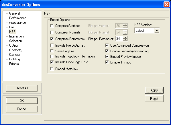
Export Options
•Compress Vertices - Compresses the vertices of entities which reduces HSF file size, but can sometimes result in visual artifacts.
•Bits per Vertex - Number of bits to be used for storing each vertex. This can be any integer between 8 & 72. This is applicable only if Compress Vertices is chosen.
•Compress Normals - Compresses the normals of entities which reduces HSF file size, but can sometimes result in visual artifacts.
•Bits per Normal - Number of bits to be used for storing each normal. This can be any integer between 8 & 72. This is applicable only if Compress Normals is chosen.
•Compress Parameters - Compresses the vertex parameters of entities which reduces HSF file size, but can sometimes result in visual artifacts.
•Bits per Parameter - Number of bits to be used for storing each vertex parameter. This can be any integer between 8 & 72. This is applicable only if Compress Normals is chosen.
•Include File Dictionary - Export the file dictionary information. File Dictionary provides random entity access capability, but usually results in marginal increase in the size.
•Use Advanced Compression - Export the HSF file using the advanced edge-breaker connectivity compression. For more details on this type of compression, please refer to the HOOPS/Stream documentation.
•Save Log File - If checked, output files called hsf_export_log.txt and hsf_import_log.txt will be created which contain a byte representing each opcode that was exported or imported during the write and/or read phase, respectively.
•Enable Geometry Instancing - If checked, identical geometry will not be enumerated separately when saving a file.
•Include Topology Information - If selected, HSFs will contain the associativity information between the graphical entities and their assembly structure. This can then be used to navigate the topological structure of the model without the need for the modeling kernel or the SAT file. Since this information is stored within the file it does increase the file size, which may be undesirable if you are streaming the files across bandwidth constrained networks.
•Embed Preview Image - Includes a simple thumbnail image which an application might load as a preview for things like file selection.
•Include Line/Edge Data - Exports non-surface data to the HSF file, such as lines, arcs, text, circles, etc... It is useful to export this data if either:
a) the data originated as an SAT file and accurate wireframe or hidden-line renderings are desired
b) much of the interesting geometry in the file is 'line data'; this would of course be the case if the model was an AEC-type model such as a 2D floorplan.
•Enable Tristrips - If checked, tristrips are generated for all faces. If unchecked, HOOPS will not make tristrips for nontriangular faces. However, if advanced compression is on, some faces may still be triangulated.
•Embed Materials - Embed hsf versions of the materials into the data.
•HSF Version - The export version number for HSF files.
Interaction Settings
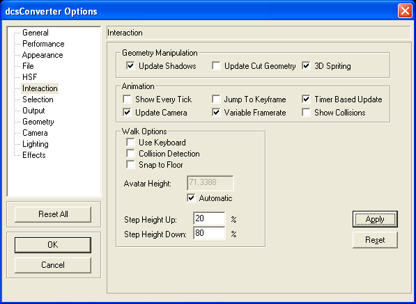
Geometry Manipulation
•Update Shadows - If checked, shadows will be updated during translation/rotation of objects.
•Update Cut Geometry - If checked, cut geometry will be updated during translation/rotation of objects.
•3D Spriting - If checked, spriting is used during translation/rotation of objects
Animation
•Show Every Tick - If checked, displays every tick of the animation regardless of the time per frame.
•Update Camera - If not checked, camera movement which is part of the animation will be suppressed
•Jump To Keyframe - If checked, the +/- button of the animation toolbar will move the animation to the next keyframe instead of the next tick
•Variable Framerate - If checked, the Constant Framerate Logic will be disabled while an animation is running.
•Timer Based Update - If checked, updates are happening on regular intervals which allows animations to interact smoothly with other user input. Turning this off can help in code debugging.
•Show Collisions - If checked, will enable visualization of collision detection in animations.
Walk Options
•Use Keyboard - Checking this enables keyboard controls for movement. Keyboard controls are as follows:
![]() W - Forward
W - Forward
![]() A - Strafe Left
A - Strafe Left
![]() S - Back
S - Back
![]() D - Strafe Right
D - Strafe Right
![]() Q - Up
Q - Up
![]() Z - Down
Z - Down
•Collision Detection - This enables collision detection between the camera and geometry in the scene.
•Snap to Floor - If checked, the walk operator will prevent the camera from floating too high over a surface, and snap to the floor when possible.
•Avatar Height - This controls the height of the camera when the camera is snapped to the floor.
![]() Automatic - Allows HOOPS to automatically set the avatar height to be a fraction of the scene extents.
Automatic - Allows HOOPS to automatically set the avatar height to be a fraction of the scene extents.
•Step Height Up - This set the height at which the avatar will automatically walk up stairs and over small obstacles.
Step Height Down - This sets the maximum height that the avatar can drop. Thus, if the drop is too large, the avatar will not be able to walk over an edge.
Selection Settings
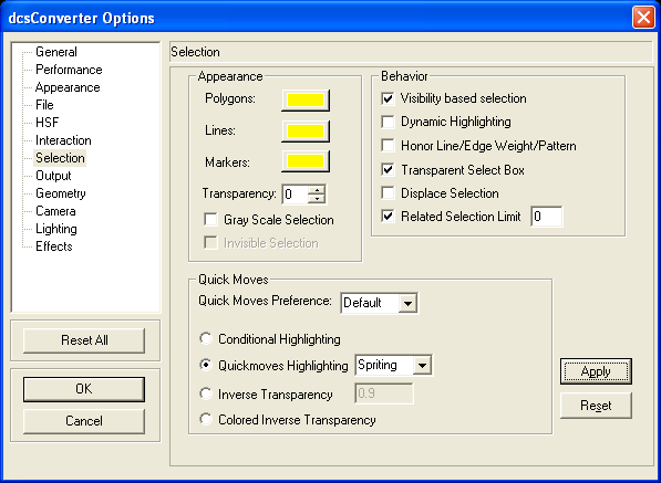
Appearance
•Polygons - Sets the selection color for polygons (faces).
•Lines - Sets the selection color for lines (edges).
•Markers - Sets the selection color for markers (vertices).
•Transparency - Sets the transparency level (%) for the selected entities.
•Gray Scale Selection - If checked, sets the scene to gray scale when performing a selection.
•Invisible Selection - If checked, everything but the highlighted item will be invisible.
Behavior
•Visibility based selection - If checked, all selection operations take visibility of objects into account (versus the standard analytical selection mode of HOOPS). Uncheck this option if everything inside the selection window needs to be deleted, otherwise only visible features will be deleted.
•Dynamic Highlighting - If checked, will automatically highlight geometry on a mouseover (and subsequently unhighlight when the mouse leaves).
•Honor Line/Edge Weight/Pattern - If checked, HOOPS will honor the weights and patterns of lines and patterns.
•Transparent Select Box - If checked, the "Select by Window" operator will display a transparent overlay.
•Displace Selection - If checked, HOOPS will rendered a selected object on top of any coincident geometry.
•Related Selection Limit - If checked, tells the system that no more than the number specified of items of geometry past the first will be needed.
Quick Moves
•Quick Moves Preference - Determines the default method of rendering quick moves.
•Conditional Highlighting - Highlights the selected items by setting a conditional style in the selected segments.
•Quickmoves Highlighting - Determines if Quickmoves should be used during highlighting. If Quickmoves is on for highlighting, specifies which method is used for rendering.
•Inverse Transparency - Leaves the selected item the same, while making everything else in the scene transparent.
•Colored Inversed Transparency - Applies the selection color on the selected item, while making everything else in the scene transparent.
Output Settings
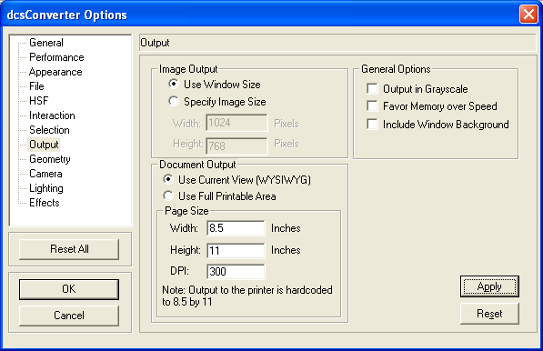
Image Output
•Use Window Size - If checked, the height and width of the current window will be used for output.
•Specify Image Size - If checked, used the specified height and width for image output.
![]() Width - Determines the width of the output.
Width - Determines the width of the output.
![]() Height - Determines the height of the output.
Height - Determines the height of the output.
General Options
•Output in Grayscale - If checked, output will appear in grayscale.
•Favor Memory over Speed - If checked, some memory-intensive optimizations will not be used when rendering output.
•Include Window Background - If checked, the window background color gradient will be output along with the model.
Document Output
•Use Current View (WYSIWYG) - If checked, the output will be exactly what is rendered into the current window.
•Use Full Printable Area - If checked, HOOPS will render as much of the model as it can into the size of the output.
![]() Page Size
Page Size
Determines the paper size. For output to a printer, the paper size is hard-coded to 8.5 by 11.
•Width - Sets the width of the paper used for output.
•Height Sets the height of the paper used for output.
•DPI - Sets the print output resolution.
Geometry Settings
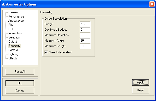
Curve Tesselation
•Budget - Sets the upper boundary of the number of vertices that will be allowed in the tesselation of the NURBS.
•Continued Budget - Sets the number of additional vertices will be allocated to the overall curve. Whereas a curve with exactly degree+1 control points will have "budget" number of vertices, curves with more control points than that number will have "continued budget" additional vertices for every extra control point.
•Maximum Deviation - Sets the distance, in object space, of the tessellation to the parametric definition of the curve. Note that since this setting is in object space, it should be set differently depending on the scale of the NURBS control points.
•Maximum Angle - Sets the largest angle allowed between adjacent line segments in the tessellated representation. Expressed in degrees.
•Maximum Length - Sets the largest allowable length, in the NURBS Curve's normalized [0, 1] parametric space, of any line segment.
•View Independent - If checked, HOOPS tesselates a NURBS curve with the number of vertices specified in "budget". Otherwise, tesselation of a NURBS curve is done as far as necessary, depending on the camera setting, in order to maintain a smooth curve. "view dependent" is more accurate, but "view independent" is computationally cheaper.
Camera Settings
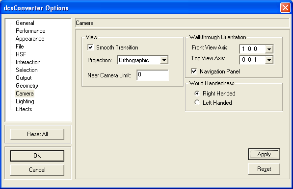
View
•Smooth Transition - If checked, the camera is transitioned between two positions smoothly (in small increments).
•Projection - Sets the camera projection.
•Near Camera Limit - Sets the near clipping distance.
Walkthrough Orientation
•Front View Axis - Sets what the partviewer will consider the "front view" for use with the "standard views" buttons.
•Top View Axis - Sets what the partviewer will consider the "top view" for use with the "standard views" buttons.
•Navigation Panel - If checked, HOOPS will display a navigation panel on the bottom right side of the window with arrows indicating directions for movement.
World Handedness
Determines the facing of polygons indicating which is the "front" or "back."
•Right Handed - If checked, the world and the axis triad with be right handed.
•Left Handed - If checked, the world and the axis triad will face opposite of right handed way.
Lighting Settings
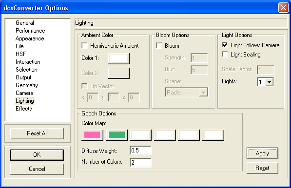
Ambient Color
•Hemispheric Ambient - If checked, HOOPS will apply ambient lighting to calculation for the color of a surface based on its normal vector and the value of the up vector which is (0,1,0) by default.
•Color1 - If Hemispheric Ambient is not checked, the color applies to the lighting calculations of all surfaces. If Hemispheric Ambient is checked, the color applies to the lightning calculation using the up vector information.
•Color2 - If Hemispheric Ambient is checked, HOOPS uses this color as the light color in the opposite direction of the up vector when performing lighting calculations for surfaces.
•Up Vector - The up direction of the Hemispheric Ambient lighting.
Bloom Options
•Bloom - When enabled, the bright objects will begin to "bleed" into darker ones, simulating the imperfect focus inevitable with the human eye or any other type of lens.
![]() Strength - This value determine the contribution of bloom to the overall color value. Numbers in the range of 0 to 10 are accepted where the higher number means more contribution.
Strength - This value determine the contribution of bloom to the overall color value. Numbers in the range of 0 to 10 are accepted where the higher number means more contribution.
![]() Blur - The number of blur passes to perform on the output. Higher values mean that bloom will affect a wider area and look smoother. Numbers in the range of 1 to 8 are accepted.
Blur - The number of blur passes to perform on the output. Higher values mean that bloom will affect a wider area and look smoother. Numbers in the range of 1 to 8 are accepted.
![]() Shape - The type of kernel used in creating the bloom effect.
Shape - The type of kernel used in creating the bloom effect.
Light Options
•Light Follows Camera - If checked, HOOPS will move lighting when the camera moves.
•Light Scaling - If checked, lighting will have a scaling factor.
•Scale Factor - A smaller factor will make the scene whiter while a larger will make the scene darker.
•Lights - The number of distant lights that will be inserted into the scene. These lights will obey the Light Follows Camera option.
Gooch Options
•Color Map - Select colors for the color map that applies to models when Gooch rendering is enabled.
•Diffuse Weight - Enter a value from 0 to 1. Regular diffuse lighting contributes weight, and the non-photorealistic lighting from Gooch contributes (1-weight).
•Number of Colors - The number of colors to use in the color map starting with the left color in the color map. You can specify whole or fractional numbers.
Effects Settings
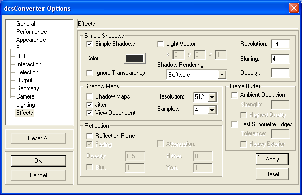
Simple Shadows
•Simple Shadows - If checked, shadows that are cast on the floor will be rendered. This is a limited functionality and shadow maps are recommended. Simple shadowing is sometimes referred to as fake shadowing, i.e. it does not rely on interpolation. Rather the shadow effect is achieved through use of texture maps.
•Color - The color of the shadow.
•Ignore Transparency - Toggles whether or not transparency is considered when casting simple shadow.
•Light Vector - the direction used to determine how the simple shadow is cast. This value is independent of all other light vectors including distant, local and spot lights added to the scene. The default value is in the positive z direction.
•Shadow Rendering - Determines the method used to render the shadow.
•Resolution - A number from 32 to 1024 that determines the resolution of the shadow.
•Blurring - A number between 1 to 31 indicating the level of blurring (softening) that is applied to the shadow.
•Opacity - A floating point value between 0 and 1 that sets the transparency of the shadow where 1 is completely opaque.
Shadow Maps
•Shadow Maps - If checked, shadows that are cast on faces are rendered.
•Jitter - If checked, HOOPS will use stochastic sampling of shadow maps. This can reduce aliasing in the shadow map.
•View Dependent - If this option is checked, the view frustum is taken into account when generating shadow maps. This can give you better quality overall but there can be a performance cost because shadow maps are generated every time the view frustrum changes.
•Resolution - The width and height of the shadow map. This value will be clamped up/down to 512, 1024 or 2048.
•Samples - The number of locations in the shadow map used to determine the percentage value of light received by a pixel in the rendered scene.
Frame Buffer
•Ambient Occlusion - If checked, shading is applied when nearby objects or occluders would prevent some portion of ambient light from reaching a surface.
•Strength - A multiplier on the default contribution of ambient occlusion. The higher the number the strong the ambient occlusion contribution.
•Highest Quality - If checked, it will use the highest quality shader that will fit within the instruction count limits for hardware acceleration, without regard to execution time. The default is set for performance.
•Fast Silhouette Edges - If checked, enables the drawing of fast silhouettes where the difference between z-buffer values of neighboring pixels is greater than a certain threshold.
•Tolerance - The threshold used when comparing adjacent pixel depth values to detect silhouettes.
•Heavy Exterior - If checked, HOOPS draws an extra thick line at the exterior silhouettes.
Reflection
•Reflection Plane - If checked, reflections against the floor are rendered.
•Fading - If selected, the reflection plane will fade as it moves away from the camera.
•Opacity - A value between 0 and 1 that determines the transparency of the reflection plane where 0 is completely transparent.
•Blur - An integer between 1 and 31 indicating the level of softening that is applied to the reflection. This option is only applies when the DX9 driver is used.
•Attenuation - Fades the reflection as the model moves away from the reflection plane. This option only applies when the DX9 driver is used.
![]() Hither - Determines the location of the near plane. This is where the attenuation begins.
Hither - Determines the location of the near plane. This is where the attenuation begins.
![]() Yon - Determines the location of the far plane. This is where the attenuation ends and the image is completely faded.
Yon - Determines the location of the far plane. This is where the attenuation ends and the image is completely faded.