Save a new file for this lesson.
•With the Analyst_Tutorial_Lesson4 tab open, Go to the North quadrant of the Compass (called My Social and Collaborative Apps) and select the Collaborative Lifecycle app.
•Select the Analyst_Tutorial_Lesson4 Simulation and select ![]() Duplicate from the toolbar at the bottom.
Duplicate from the toolbar at the bottom.
•Right-click on the new duplicated Analyst_Tutorial_Lesson4 Simulation in the model tree and select Properties.
•In the Reference tab of the Properties dialog, change the Title to "Analyst_Tutorial_Lesson5".
•In the Compass, go to the South Quadrant (called My Content and Simulation Apps) and select 3DCS Variation Analyst V6 in the V+R My Simulation Apps section to return to the 3DCS Variation Analyst workbench.
•Go to File ![]() Save Management.
Save Management.
•Select the Lesson4.CATProduct and select [Save As...].
•In the Save As dialog, rename the Product to "Lesson5.CATProduct" and click [Save].
•In the Save Management dialog select [OK] to save the CATIA Product under its new name. The model is not saved until you click OK.
•Click the ![]() Application Button then select
Application Button then select ![]() Save As.
Save As.
•Change the File Name to "Lesson5.wtx".
•Click [Save] in the Save As dialog.
•Go to File ![]() Save As.
Save As.
•In the Save a Copy dialog, enter "Lamp_SubAsm_Lesson5" for the File Name, make sure the Type is set to Assembly (*.asm), then click [OK].
•In the Assembly Save a Copy dialog, click [Save Copy and Open] to save the assembly under its new name, and open the newly saved assembly.
•Close the 3DCS Model Navigator and Creo window for Lamp_SubAsm_Lesson4.
•Click ![]() Update Model in the new window for Lamp_SubAsm_Lesson5.
Update Model in the new window for Lamp_SubAsm_Lesson5.
•Go to File ![]() Save As.
Save As.
•In the Save As dialog, enter "Lamp_SubAsm_Lesson5" as the new File name and make sure the type is set to Part Files (*.prt).
•Click [OK] in the Save As dialog.
•Click ![]() Update Model.
Update Model.
•Go to File ![]() Save As.
Save As.
•In the Save as dialog, enter "Lamp_SubAsm_Lesson5" for the File Name, make sure the Type is set to Assembly.
•Click [Save] in the Save As dialog.
•Click ![]() Update Model.
Update Model.
This tutorial follows the ASME standard for defining GD&T. For other models, you can change the standard in the ![]() Preferences in the Model Settings category.
Preferences in the Model Settings category.
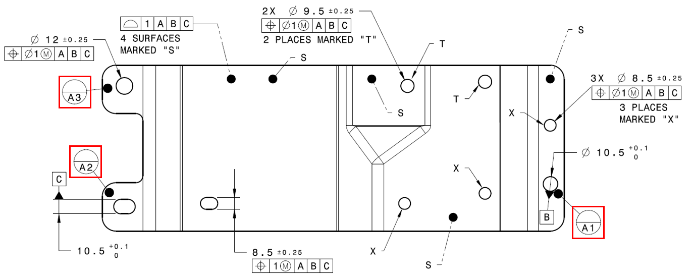
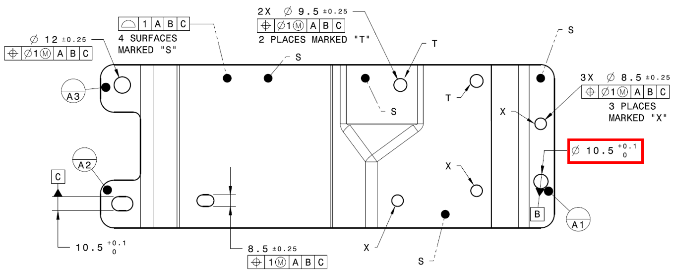
We will add variation to the Bracket using GD&Ts on the surfaces of the part. Recall that Feature Points will vary with the surfaces while Coordinate Points will not. Coordinate Points must be directly added to a GD&T in order for them to vary. GD&T will be added to the Bracket according to the print shown below.

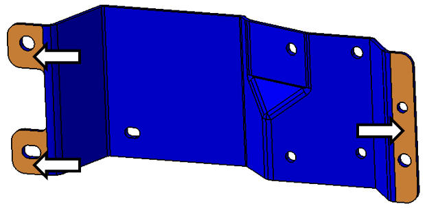
First, we must define the datum features of the Bracket. The datum features need to be defined before we can created the datum reference frame (DRF) for the other callouts. We will start with the A datum features which are highlighted in the image below.
•Click ![]() GD&Ts then select the Bracket. This will open the GD&Ts dialog.
GD&Ts then select the Bracket. This will open the GD&Ts dialog.
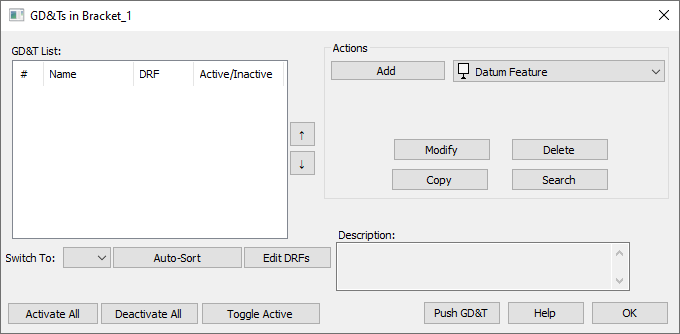
•Select Datum Feature as the type from the drop-down list next to [Add].
•Click [Add]. This will open the GD&T dialog for Datum Features.
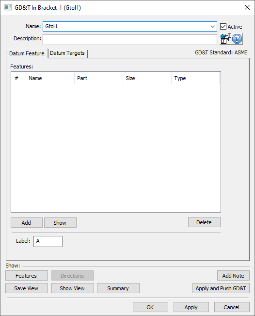
•Change the Name to "Datum_A".
•In the Datum Feature tab, select [Add].
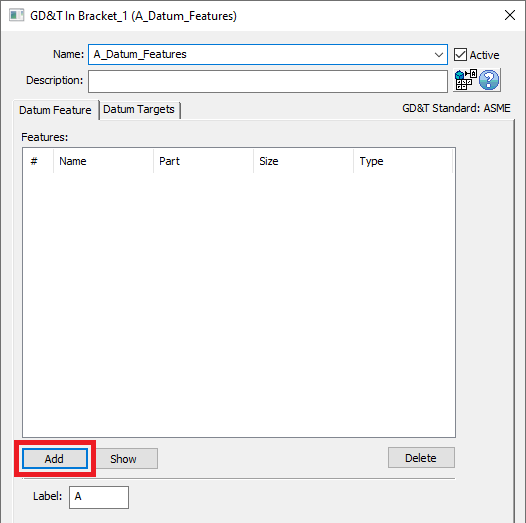
•Select the three surfaces highlighted in the image below. These surfaces are the A datum features in the print.
•Click [Close] in the Select dialog.
•Verify the Label is "A".
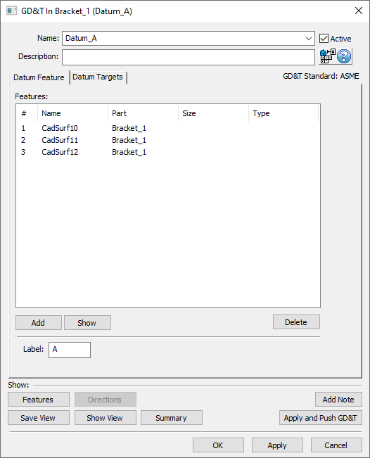
The completed GD&T dialog should look like the image below. Your CadSurf numbers may be different.
•Select [OK] in the GD&T dialog.
Next, we will add the size tolerance for the B datum feature.
•Select Size as the type from the drop-down list next to [Add] in the Actions area.
•Click [Add]. This will open the GD&T dialog for Size.
•Change the Name to "Size_Datum_B".
•In the Tolerance tab, in the Features section, click [Add].
•Click the hole highlighted in the image below (click the cylindrical surface, not the edge).

•Click [Close] in the Select dialog.
•Select Ø Diametrical for the zone type.
•Enter 0.1 for Upper value.
•Uncheck Symmetric (so there is no check in the checkbox).
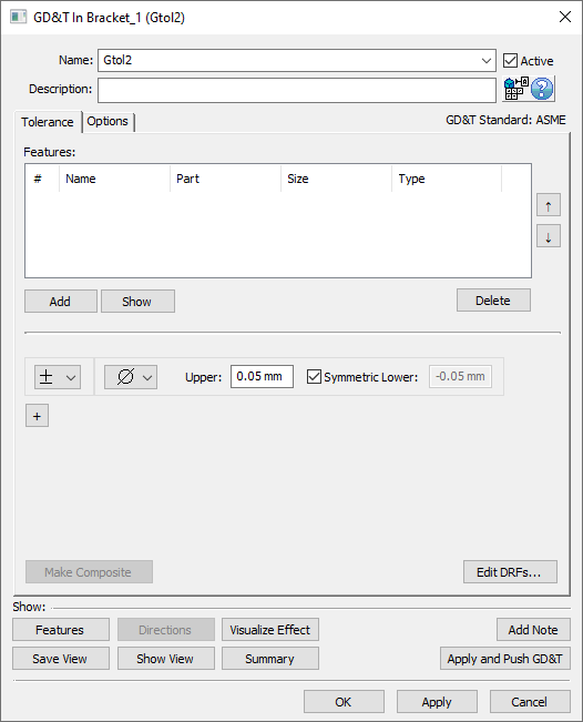
•Enter 0mm for the Lower value. The completed dialog should look like the image below. Your CadSurf number may be different.
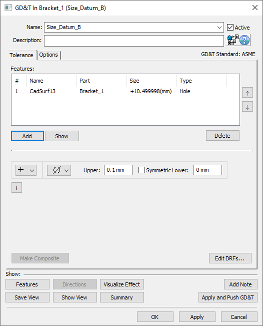
•Click [OK] in the GD&T dialog.
That is all we need for the size tolerance. Now, we will specify the hole as the B datum feature.
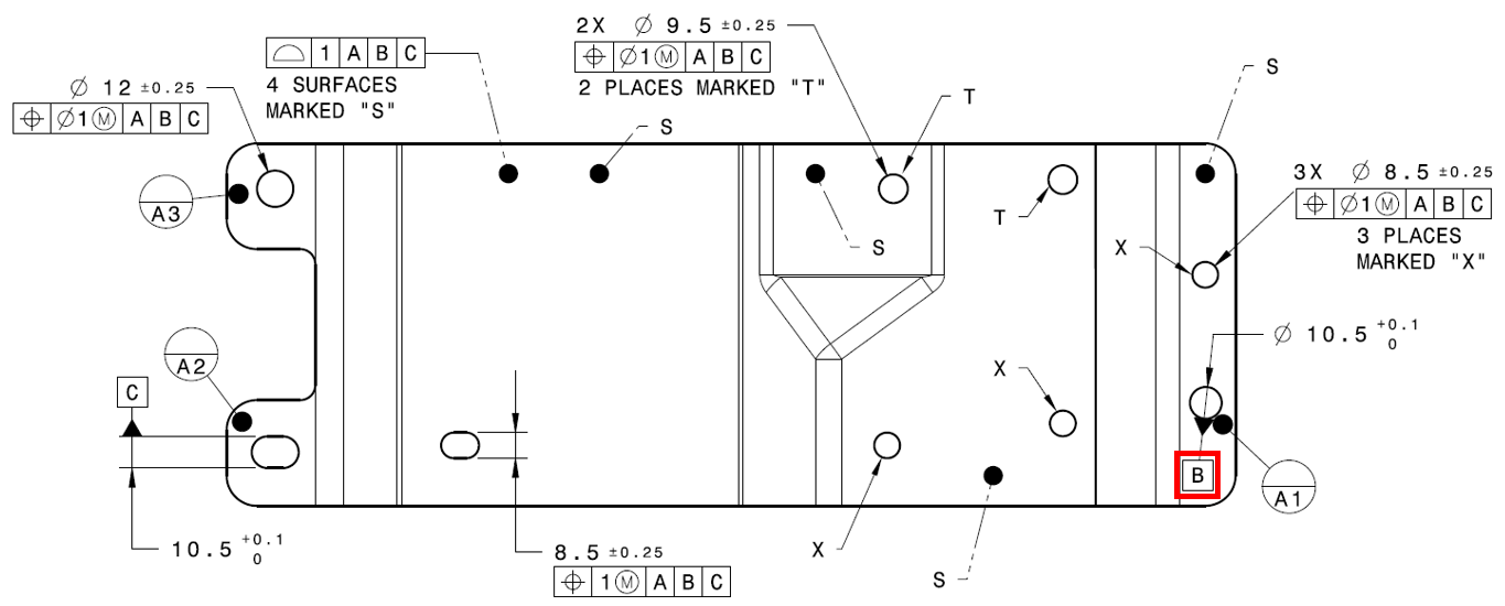
•In the GD&Ts dialog, select Datum Feature as the type.
•Click [Add]. This will open the GD&T dialog for Datum Features.
•Change the Name to "Datum_B".
•In the Datum Feature tab, click [Add] in the Features section.
•Click the same hole used for the size tolerance (highlighted in the image below).

•Click [Close] in the Select dialog.
•Verify the Label is "B".
•Click [OK] in the GD&T dialog.
Datum feature C is a slot. We will create the size tolerance on it next.
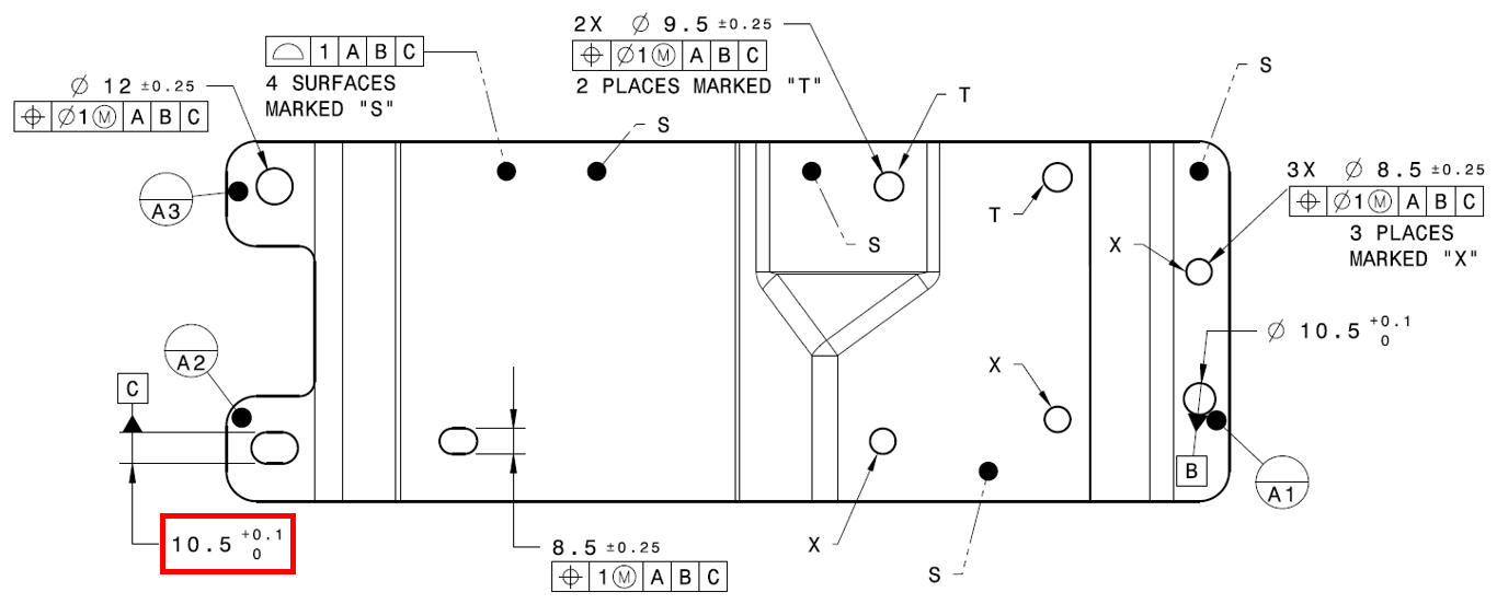
•In the GD&Ts dialog, select Size as the type from the drop-down list.
•Click [Add].This will open the GD&T dialog for Size.
•Change the Name to "Size_Datum_C".
•In the Tolerance tab, click [Add] in the Features section.
•Select the slot O_Fixture_Z in the Bracket. You can select the slot in the tree or in the graphics. Alternatively, you could select the two surfaces that were used to define the slot.
•Click [Close] in the Select dialog.
•Select blank (not diametrical or spherical) for the zone type.
•Enter 0.1 for the Upper value.
•Uncheck Symmetric (so there is no check in the checkbox).
•Enter 0mm for the Lower value. The completed dialog should look like the image below.
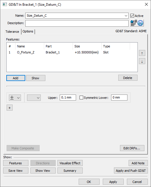
•Click [OK] in the GD&T dialog.
Now, we will specify the slot as the C datum feature.
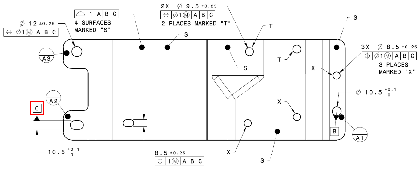
•In the GD&Ts dialog, select Datum Feature as the type.
•Click [Add].
•Change the Name to "Datum_C".
•In the Datum Feature tab, click [Add] in the Features section.
•Select the slot O_Fixture_Z in the Bracket.
•Click [Close] in the Select dialog.
•Click [OK] in the GD&T dialog.
Now we will add the surface profile for the four surfaces of the Bracket that the Headlamp and Turnlamp contact.
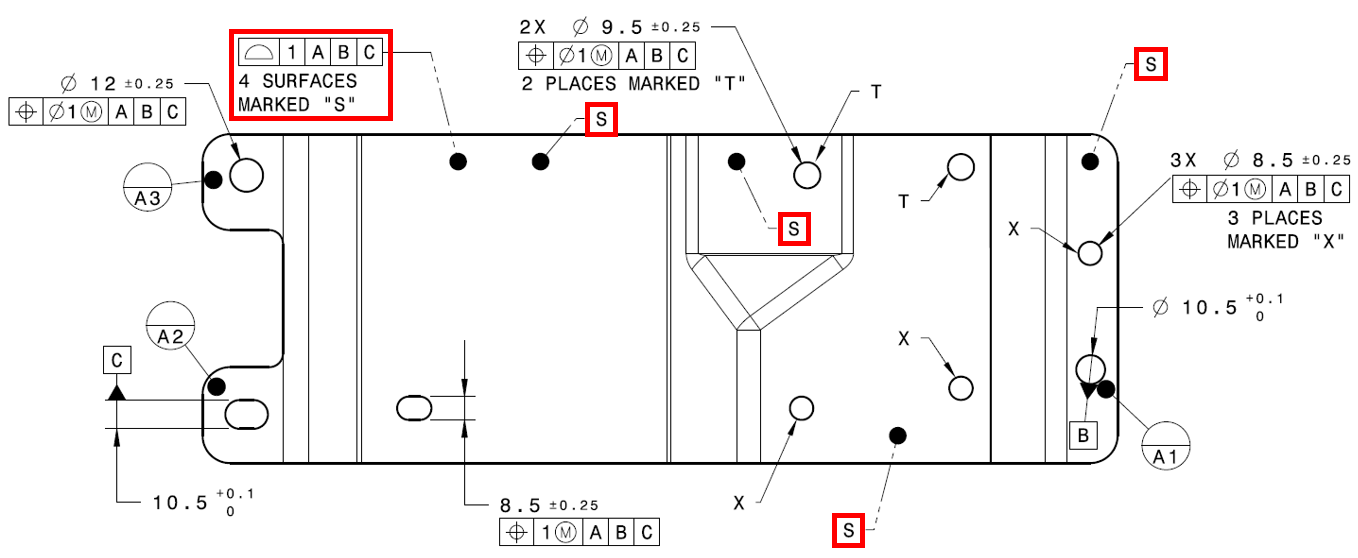
•In the GD&Ts dialog, select Surface Profile for the type and click [Add].
•Change the tolerance Name to "Surface_Profile".
•In the tolerance Description, enter "Surface profile at mounting holes."
•In the Tolerance tab, click [Add] then select the four surfaces of the Bracket highlighted below (every feature marked "S" in the drawing). The order does not matter. These surfaces control the variation of the primary planes to the two lamps.
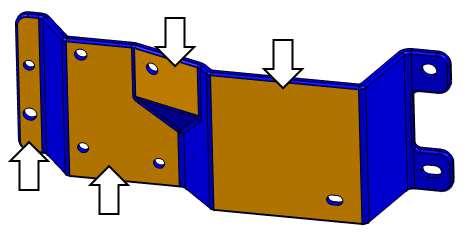
•Click [Close] in the Select dialog.
•Set the Range to 1 mm.
We haven't created a datum reference frame (DRF) yet so we will do that now.
•Select the [Edit DRFs...] button in the lower-right of the Tolerance tab.
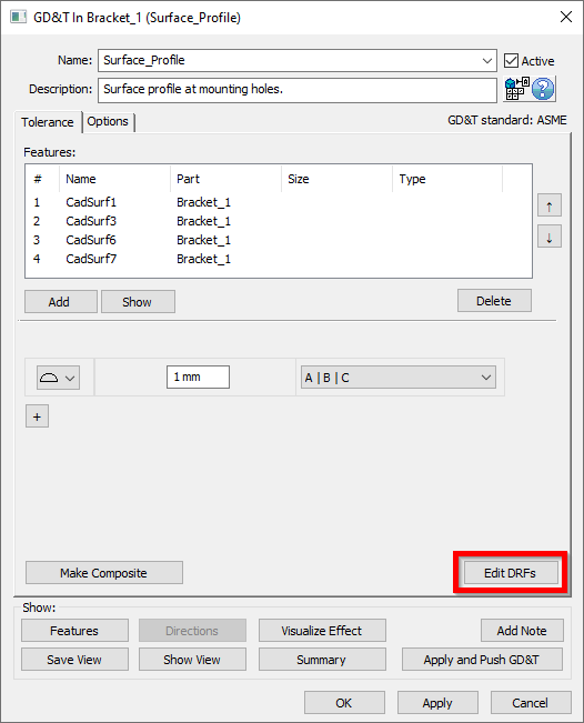
•In the Datum Features list of the Edit DRFs dialog, click Datum_A. This will add the label "A" to the first DRF field.
•Next select Datum_B then Datum_C. This will add the labels "B" and "C" to the second and third DRF fields.
•Click [Add]. This will add a DRF with reference A | B | C to the Datum Reference Frames list. This can now be used in the tolerance.
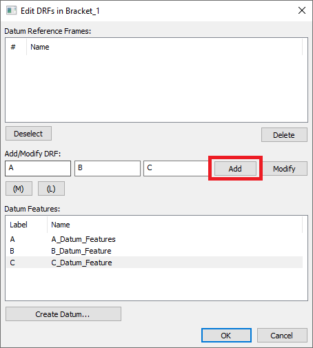
•Select the [OK] to return to the GD&T dialog.
•Select A | B | C from the drop-down menu to set it as the DRF for the profile tolerance. The completed dialog should look like the image below. Your CadSurf numbers may be different.
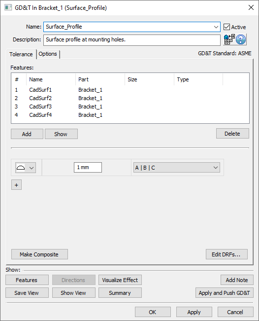
•Click the [Options] tab in the GD&T dialog.
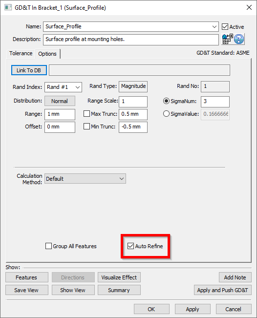
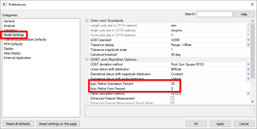
You will notice that the Auto Refine check box is checked on by default. Per the ASME standard, Surface Profile varies Location, Orientation and Form. In 3DCS, we use the Auto Refine setting to help vary all of these. With Auto Refine turned off, Surface Profile only varies Location. With it checked on, by default, Surface Profile will vary Orientation at 25% of the overall tolerance, and Form at 0%. These settings can be changed in the Preferences dialog as seen in the image below.
•Click [OK] in the GD&T dialog.
Next we will add Size and Position tolerances for the holes to the Headlamp and Turnlamp. The tolerances will be created according to the call outs highlighted below. Because the Size and Position are the same tolerances, only applied on different nominal size holes, we can create the tolerances for all five holes at the same time. However, we will create these separately to better understand which individual tolerance is contributing to our results.
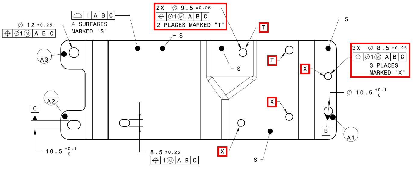
It can be good modeling practice and is helpful when looking at results to group the features by their function. In this case, we have five holes, three are used to mount the Turnlamp, and two are used to mount the Headlamp, so we will create two separate callouts in 3DCS. First we will create the Turnlamp holes callout.
•In the GD&T list dialog, select Size for the type and click [Add].
•Change the Name to "Size_Turnlamp_Holes".
•For the Description, enter "Size of Turnlamp mounting holes.".
•Click the [Add] button then select the three holes of the Bracket highlighted below (the holes associated with the Turnlamp).
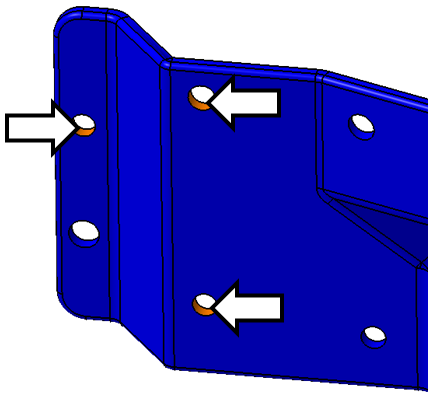
•Click [Close] in the Select dialog.
•Set the Upper to 0.25.
•Leave the Symmetric checkbox checked. This makes the Lower symmetrically opposite at -0.25.
This completes the size tolerance. Now we will add the position.
•Click [+] to add a new frame.
•Change the name to "Position_Turnlamp_Holes".
•Add a description of "Position of Turnlamp mounting holes.".
•In the new frame, change the type to ![]() Position.
Position.
•Set the zone type to Ø diametrical,.
•Set the Range to 1.
•Select ![]() Maximum Material Condition as the material condition
Maximum Material Condition as the material condition
•Select A | B | C as the DRF. Each DRF only has to be defined once then it can be reused for multiple tolerances.
The completed Size and Position tolerances for the Turnlamp holes in the Bracket will look like the image shown below. Your CadSurf number may be different.
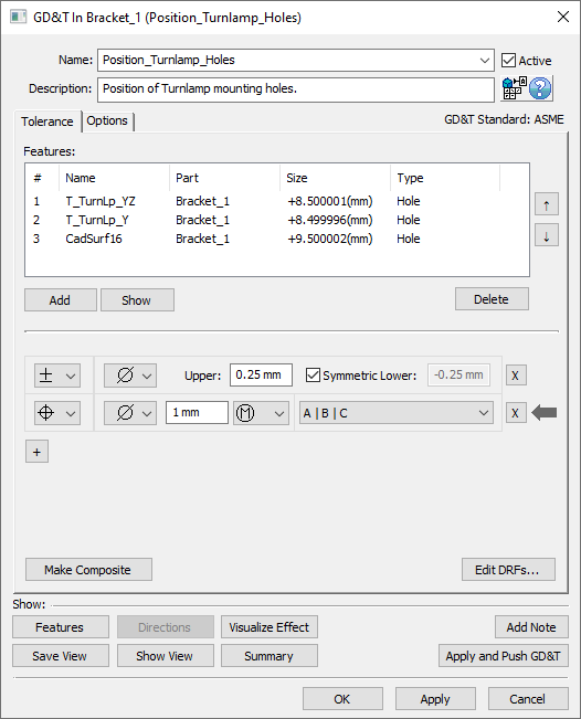
•Click [OK] in the GD&T dialog Size and Position tolerances.
Next we have to add the size and position tolerance to the two Headlamp mounting holes. The two holes included in these tolerances are highlighted below.
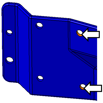
•Repeat the steps from above to create a size tolerance called "Size_Headlamp_Holes" and description "Size of Headlamp mounting holes."
•Repeat the steps from above to create a position tolerance called "Position_Headlamp_Holes" and description "Position of Headlamp mounting holes."
The completed Size and Position tolerances for the Headlamp holes in the Bracket will look like the image shown below. Your CadSurf number may be different.
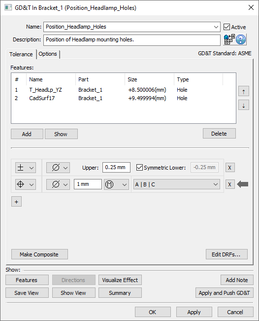
Now the slot that is used to locate the Headlamp needs to be toleranced with Size and Position.

•In the GD&Ts dialog, select Size as the type then click [Add].
•Change the Name to "Size_Slot".
•Change the Description to "Size of Headlamp mounting slot.".
•Click [Add] and select the feature slot T_HeadLp_Z in the Bracket. You can select this from the graphics window or the tree3DCS Model Navigator.
•Click [Close] in the Select dialog.
•Select blank for the zone type.
•Set the Upper to 0.25 and leave the Symmetric checkbox checked.
•Click [+] to add a new frame.
•Change the name to "Position_Slot".
•Add a description of "Position of Headlamp mounting slot.".
•Change the new frame tolerance type to ![]() Position.
Position.
•Set the zone to blank, set the Range to 1, set ![]() Maximum Material Condition as the material condition, and select A | B | C for the DRF.
Maximum Material Condition as the material condition, and select A | B | C for the DRF.
The completed Size and Position tolerances should look like the image below.
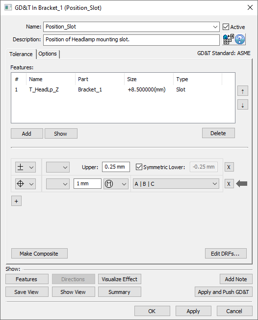
•Click [OK] in the GD&T dialog for Slot Position.
The GD&Ts dialog should look like the following image.
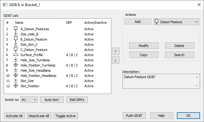
•Click [OK] in the GD&Ts dialog.
By creating our Moves and Measures before inputting our GD&T into the model, we were able to focus on only the important features for the specific analysis we were investigating. There may be another analysis that would require other tolerances we left out of our model, but for the gap Measures that we established as the scope of this analysis it would've been unnecessary work to add in other tolerances from a drawing.
Another way to verify that all features important to our model are accounted for is to check them using the ![]() Relationships tool (typically located under
Relationships tool (typically located under ![]() Validate).
Validate).
•Select ![]() Relationships from the Tools toolbar to open up the Relationships dialog.
Relationships from the Tools toolbar to open up the Relationships dialog.
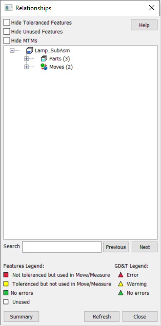
•Expand the Parts section then expand Points and Features under Bracket (if not already expanded).
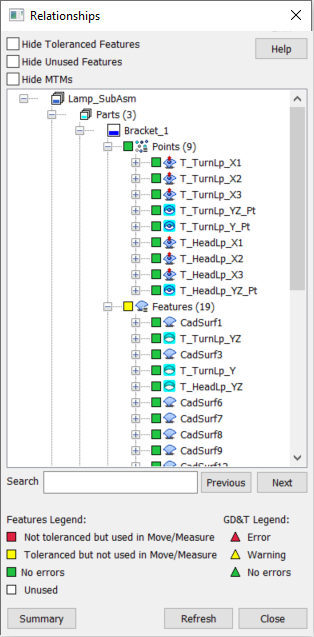
The Relationships Tree has several different functions but the primary one being used in this lesson is to verify that all the important points features in the model are included in a GD&T we've created. There are four possible colors used in the Relationships Tree to communicate to us how complete our model is.
Red indicates that we have a point or feature that is used in a Move or Measure and therefore is critical to our model, however that feature is not associated to any GD&T.
Yellow indicates that we have a point or feature that is not used in a Move or Measure but it is associated to a GD&T. Note: Yellow may imply that the point or feature and associated GD&T are not important to the model, but occasionally a yellow feature is actually still important to the model so be sure to double check before deleting any yellow points or features.
Green indicates that we have a point or feature that is used in a Move or Measure and is associated to a GD&T.
White indicates that we have a point or feature that is not used in a Move or Measure and is not associated to a GD&T. Unlike with yellow, it is a very safe bet that this point or feature is unnecessary to the model.
Notice that for the Bracket where we have added all the necessary GD&T we do not have any Red features. There are some Yellow features indicating that a part has GD&T but is not used in a Move or Measure but most of our points and features are Green.
•Expand Points and Features under Headlamp as well as Turnlamp.
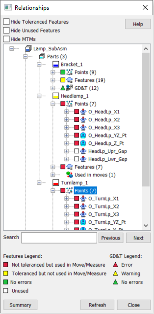
For the Headlamp and the Turnlamp we have not created any GD&T yet so all of the points and features are correctly Red, as all of the points and features in these two parts are used in a Move or Measure. In the following section we will address these parts and then revisit the Relationships Tree to verify we have not missed anything, as is a good practice to use while modeling.
•Select [Close] in the Relationships dialog.
You can visualize the tolerances on the parts to verify they are varying as intended.
•If the mesh is off, click ![]() Show Mesh to turn the mesh on.
Show Mesh to turn the mesh on.
•Switch to ![]() Creation Mode if not already there.
Creation Mode if not already there.
•Click the ![]() Deviate button.
Deviate button.
•Zoom in on the Bracket to inspect the deviating features.
•Click [Close] in the Deviate dialog after you have verified the features are deviating as expected.
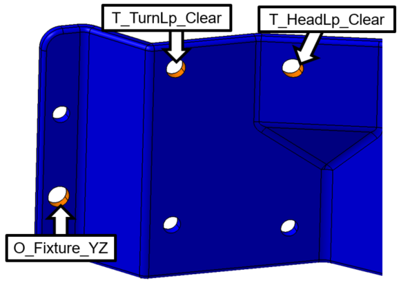
•Rename the new hole features in the Bracket according to the image below.
•Save the model.