Now we will add GD&T to the Headlamp.
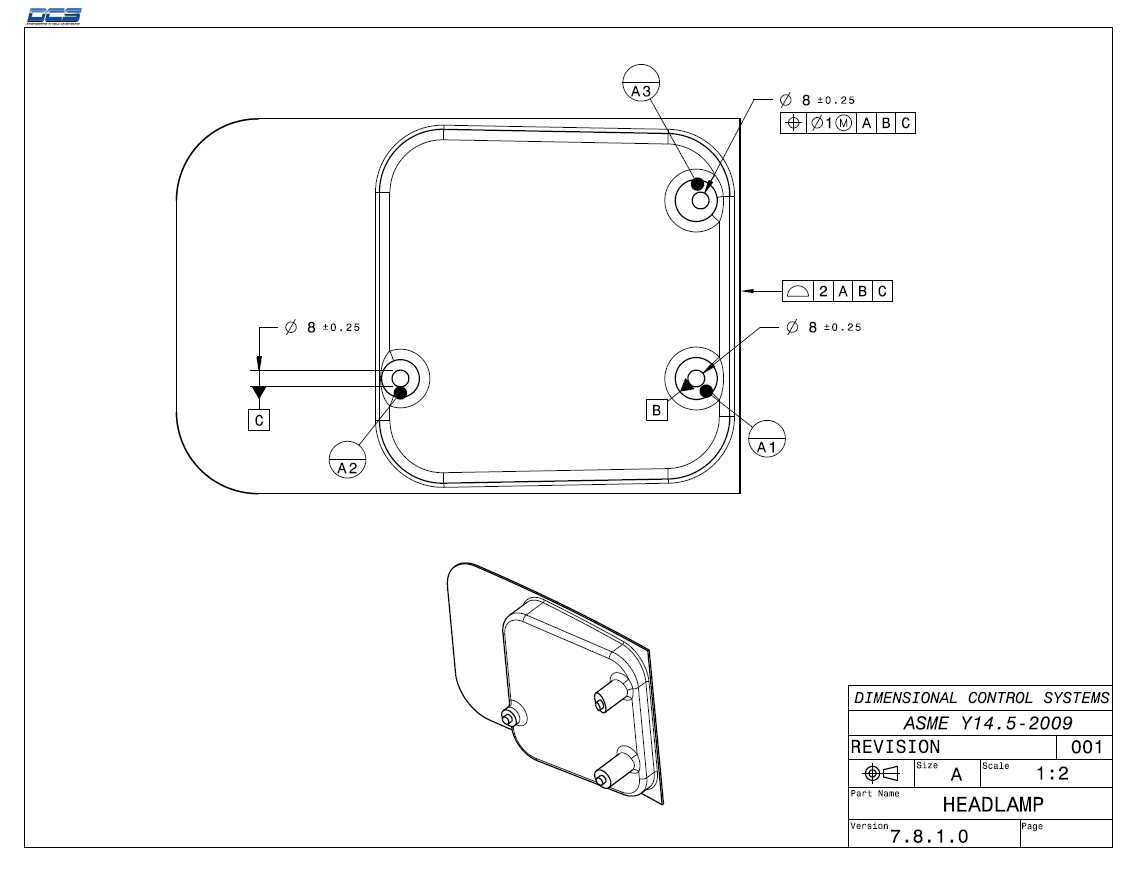
First we will define the A datum features.
•Click the ![]() GD&Ts button then select the Headlamp.
GD&Ts button then select the Headlamp.
•Select Datum Feature from the drop-down list then click [Add].
•Change the name to "Datum_A".
•In the Datum Feature tab, in the Features section, click [Add].
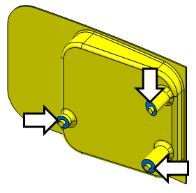
•Select the three surfaces highlighted in the image below. These surfaces are the A datum features in the print.
•Click [Close] in the Select dialog.
•Verify the Label is "A".
The completed GD&T dialog should look like the image below. Your CadSurf numbers may be different.
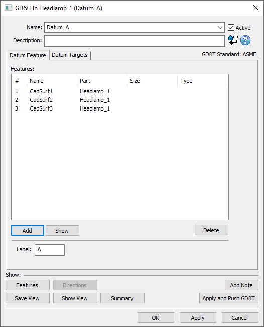
•Click [OK] in the GD&T dialog.
Next, we will add the size tolerance for the B datum feature.
•Select Size from the drop-down list then click [Add].
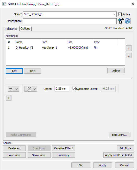
•Change the Name to "Size_Datum_B".
•In the Tolerance tab, in the Features section, click [Add].
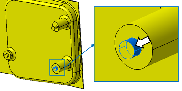
•Select the feature O_HeadLp_YZ in the Headlamp.
•Click [Close] in the Select dialog.
•Select Ø diametrical for the zone type.
•Set Upper to 0.25 and leave the Symmetric checkbox checked. The completed Size tolerance should look like the following image.
•Click [OK] in the GD&T dialog.
Now define the feature as the B datum.
•Select Datum Feature from the drop-down list then click [Add].
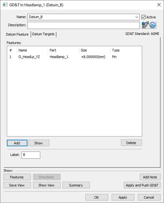
•Change the name to "Datum_B".
•In the Datum Feature tab, in the Features section, click [Add].
•Select the feature O_HeadLp_YZ in the Headlamp.
•Click [Close] in the Select dialog.
•Verify the Label is "B".
The completed GD&T dialog should look like the image below.
•Click [OK] in the GD&T dialog.
Next, we will add the size tolerance for the C datum feature.
•Select Size from the drop-down list then click [Add].
•Change the Name to "Size_Datum_C".
•In the Tolerance tab, in the Features section, click [Add].
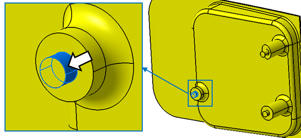
•Select the feature O_HeadLp_Z in the Headlamp.
•Click [Close] in the Select dialog.
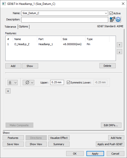
•Select Ø diametrical for the zone type.
•Set Upper to 0.25 and leave the Symmetric checkbox checked. The completed Size tolerance should look like the following image.
•Click [OK] in the GD&T dialog.
Now define the feature as the C datum.
•Select Datum Feature from the drop-down list then click [Add].
•Change the name to "Datum_C".
•In the Datum Feature tab, in the Features section, click [Add].
•Select the feature O_HeadLp_Z in the Headlamp.
•Click [Close] in the Select dialog.
•Verify the Label is "C".
The completed GD&T dialog should look like the image below.

•Click [OK] in the GD&T dialog.
Next, we will create the size and position tolerances for the clearance pin (the upper, outboard pin).
•Select Size from the drop-down list then click [Add].
•Change the Name to "Size_Clearance_Pin".
•In the Tolerance tab, in the Features section, click [Add].
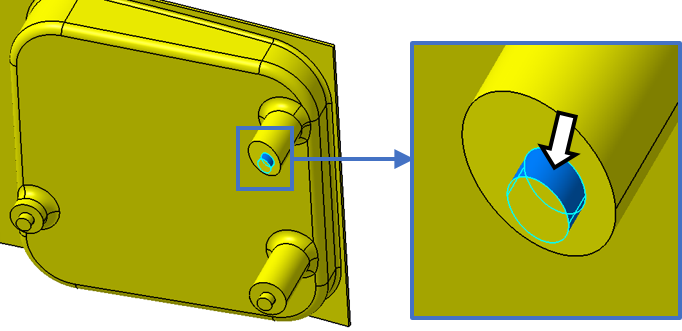
•Select the pin in the Headlamp highlighted in the image below.
•Click [Close] in the Select dialog.
•Select Ø diametrical for the zone type.
•Set Upper to 0.25 and leave the Symmetric checkbox checked.
•Click [+].
•Change the Name to "Position_Clearance_Pin".
•In the second frame, change the type to ![]() Position.
Position.
•Select Ø diametrical for the zone type, set the Range to 1, and select ![]() Maximum Material Condition for the material condition.
Maximum Material Condition for the material condition.
•Select [Edit DRFs...] and create the A | B | C DRF in the Edit DRFs dialog.
•Select [OK] to return to the GD&T dialog.
•Select A | B | C as the DRF.
The completed Size and Position tolerances will look like the image shown below. Your CadSurf number may be different.
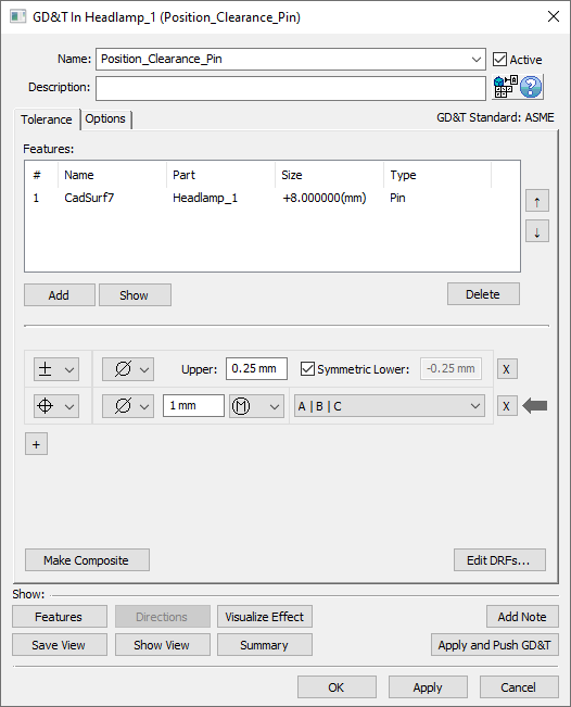
•Click [OK] in the GD&T dialog.
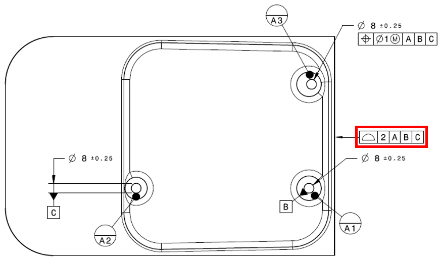
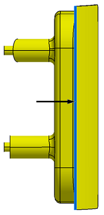
Finally, we will create the surface profile tolerance for the gap surface to the Turnlamp.
•Select Surface Profile from the drop-down list then click [Add].
•Change the Name to "Surface_Profile".
•Add the Description "Surface profile on trim surface.".
•In the Tolerance tab, in the Features section, click [Add].
•Select the feature HL_TrimSurface of the Headlamp highlighted in the image below.
•Click [Close] in the Select dialog.
•Set the Range to 2.
•Select A | B | C as the DRF.
The completed Size and Position tolerances will look like the image shown below. Your CadSurf numbers may be different.
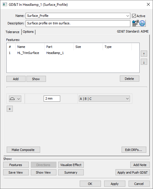
•Click [OK] in the GD&T dialog.
The complete list of GD&Ts should look like the following image.
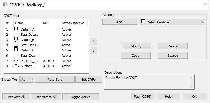
•Click [OK] in the GD&Ts dialog.
•If the mesh is off, click on ![]() Show Mesh to turn the mesh on.
Show Mesh to turn the mesh on.
•Go to ![]() Creation Mode if not already there.
Creation Mode if not already there.
•Click the ![]() Deviate button.
Deviate button.
•Zoom in on the Headlamp to inspect the deviating features.
•Click [Close] in the Deviate dialog after you have verified the features are deviating as expected.
•Rename the new pin feature (the upper, outboard pin) in the Headlamp according to the image below.
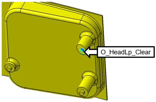
•Save the model.