In the real world, tolerances limit the variation that is inherent in manufacturing. In 3DCS, tolerances add variation to the nominal geometry. The tolerances used in the model can come from actual measured parts, from the detail tolerances allowed on the prints, or from "what if" scenarios (which may result in changes to the detail prints). Ideally, each completed detail print will limit the piece-part variation so that the assembly will be in-spec - within the allowable limits of variation. Therefore, it is useful to understand how the variation at the part level affects the variation at the assembly level.
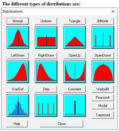
Deviations of a part will not always be at the maximum or minimum values of the tolerance. If part variation is assumed to have a normal distribution, then deviations have a high probability of being close to nominal and less than 0.3% of parts will be at or beyond the tolerance limits if checked at ±3σ (where σ is the standard deviation). If checked at ±4σ, then less than 0.01% of parts will be at or beyond the tolerance limits. So, an arithmetic stack-up of the worst-case detail tolerances is very conservative. The reality of using the worst-case print values to predict assembly variation can be very expensive and unnecessary. A normal distribution is not always the most accurate way to simulate the real-world variation of a part so 3DCS has many distribution options to best represent the variation from manufacturing.

In a 3DCS model, variation is added to a part with GD&T. 3DCS GD&T adds variation to a feature's location, orientation, or form with respect to datum references. 3DCS GD&T can be authored in 3DCS or extracted from the CAD software's product manufacturing information (PMI). This is called Functional Tolerancing & Annotation (FT&A) in CATIA V5.