Input requirements: Measure Type: Center Distance, Min Distance, Max DistanceGeometry Requirement: CAD Surfaces: Planes, Cylinders, Spheres, Slot/Tabs), Feature Points, Coordinate Points.Direction Type: Auto (Default), Custom DirectionSpec Limits: Required.
|
Selection Mode:•Feature selection can be done by either directly selecting the CAD Surface •Point at Click method creates a point on the surface at the mouse click location and uses that point in the measure. Direction options:Constant Direction Custom Direction Other examples
|
Supported Features and Modes:
Plane to Plane - Distance is defined when measuring from Plane to Plane. Dimensional Distance is only going to measure from the Feature Center of the plane along the direction of the plane.
Direction- Auto, Measuring direction is from the first Feature selected.
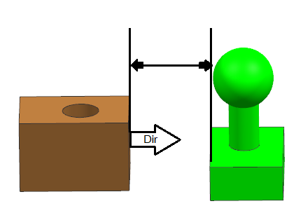
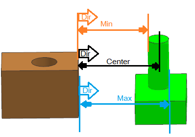
Plane to Cylinder- Center, Min and Max distance can be calculated for this pair type.
Direction- Auto, Measuring direction is always from the Plane feature.
Plane to Spheres- Center, Min and Max distance can be calculated for this pair type.
Direction- Default, Measuring direction is always from the Plane feature.
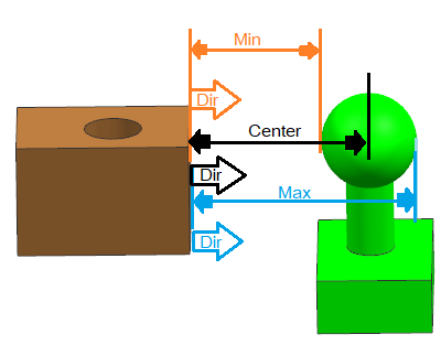
Cylinder- Sphere - Center, Min and Max distance can be calculated for this pair type.
Direction- Default, Measuring direction is calculated by taking the axis of the Axis features and projecting it to a perpendicular plane onto which the Point of the Sphere is also projected. The measure direction is then established by the vector from the axis projected point to the projected sphere center point. Then the direction is set to Constant direction during Nominal Build (Direction will not change during deviation).
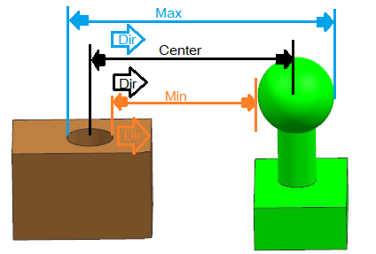
Two Cylinders - Center, Min and Max distance can be calculated for this pair type.
Directions (Default): Measuring direction is calculated by taking the axis of Feature 1 and projecting it to a perpendicular plane onto which the axis of Feature 2 is also projected. The measure direction is then established by the vector between these two projected points, at Nominal. Then the direction is set to Constant direction during Nominal Build (Direction will not change during deviation).
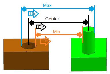
Cylindrical Feature examples |
|
|
|
With Perpendicularity |
Example |
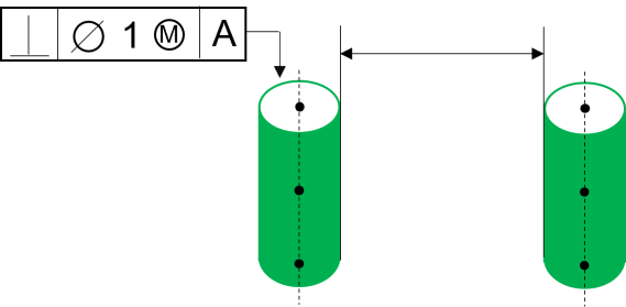
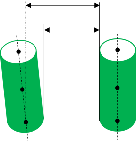
In this case and similar cases with Cylindrical features, 3DCS will generate 3 Points at the top, center and bottom along the cylinder axis. This will show Contribution from Orientation type tolerances like Perpendicularity. |
|
Direction options: When no option is specified, the Associative vector direction will be used. The Associative direction is a dynamic direction. The Associative Direction is affected by orientation tolerances.
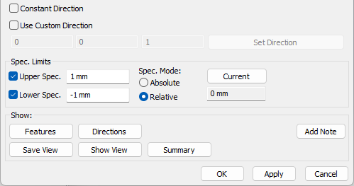
Constant Direction: With this option, the vector direction of the Object feature will be taken as the Constant direction and will remain constant. For example: when an Orientation tolerances exist on the part or feature, this direction will stay constant, not reporting any variation from the Orientation tolerance. This is only applicable to Planar features.
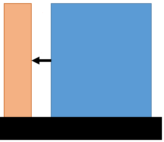
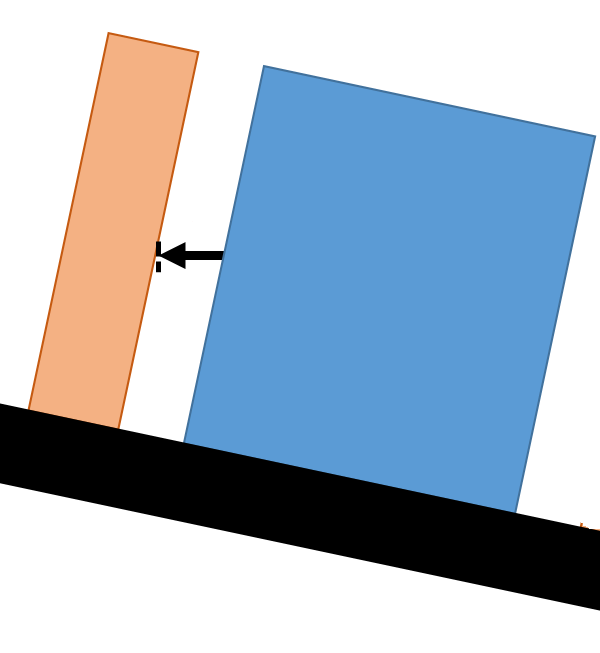
Custom Direction: User can also select direction by picking a feature. The Custom Direction will not be affected by Orientation tolerances.
Examples:
Direction for Coaxial Features:
•If two coaxial holes, Pins or Hole/pin, are selected as the features and there is no Custom Direction provided, then the measure direction will be Associative and any direction perpendicular to the axial direction.
Two Spheres - Center, Min and Max distance can be calculated for this pair type.
Direction: Does not have a direction and True Distance will be measured
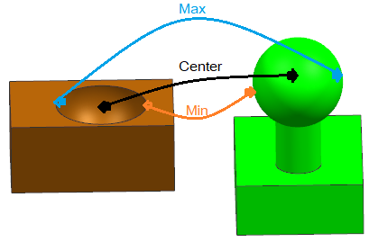
Geometric Center: The Dimensional Distance measure uses the Geometric Center of a surface. If using the two planar features to measure:
•The direction will automatically be set and always use the plane direction; when either feature is a plane in the Measure.
•While Nominal build, the direction will be normal to the feature and while deviating it becomes Constant.
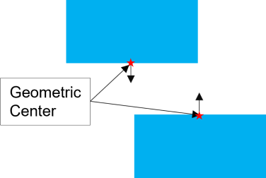
Other cases and examples |
|
|
|
Case 1 |
Case 2 |
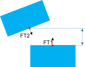
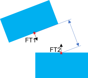
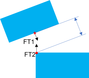
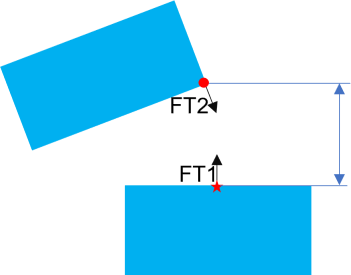
In these examples, two measures are using the same feature, but the measure inputs are different.
•Case 1: Feature 1 (FT1) is the normal plane and Feature 2 (FT2) is the tilted plane.
•Case 2: Feature 1 (FT1) is the tilted plane and Feature 2 (FT2) is the normal plane.
Best Practices:
Utilize the Point at Click option and knowing how the direction is applied to the feature. You can create two measures, one at each end of the two parts.
Examples |
|
|
|
Case 1: Min Distance |
Case 2: Max Distance |
•Case 1 - Min Distance: Feature 1 (FT1) is the tilted plane and Feature 2 (FT2) is the normal plane. Create a point using Point at Click for FT1, on the surface near the closest edge to the tilted part. The direction will be perpendicular to the titled plane, measuring to the edge of the second part.
•Case 2 - Max Distance: Feature 1 (FT1) is the normal plane and Feature 2 (FT2) is the titled plane. Create a point using Point at Click for FT1, on the surface, near the farthest edge of the normal part. The direction will be perpendicular to the normal part surface.
