For minimum clearance check this measurement should have the LSL = 0 and USL = N/A with the Spec. Mode set to Absolute, since this is a radial check looking for crashes between the pin and the hole/slot.
Within this section:
Example Models:C:\Users\Public\Documents\DCS\3DCS_V5_8_2_0_0\3DCS CAD & Example Models\Reference Models\Measures\Circle Interference
See Also:Interference in Move Options DE Focus Article: Circle Interference: A Non-Linear Measure
|
Input Information
Geometry Requirements: Center Points; Cylindrical Features; Tab/Slot Features
Measure Type: Clearance or interference check
Direction: One direction
The input consists of two groups of points, Objects and the Targets. The points or features in the two groups have to match each other by design and must be in order.
•Select Add to add Objects or Target points/features. This defines the hole, pin, slot or tab interference match condition to be checked.
•The Object points and Target points must be in order.
•The Objects points must match the Target points by design.
•For Min Clearance, Max Clearance and Interference Modes, set the Specification Limits to Absolute with the Lower Specification Limit (LSL) set to 0. The Upper Specification Limit (USL) should be set to a number larger than the nominal value.
•If Associated Direction is selected, the Associated Direction of each target feature is used. The corresponding object is treated as parallel to the target.
•For Interference measure the Specification Limits have no influence over the simulation results. Set the Specification Limits on Absolute and at zero value.
Changing the Spec Mode to Absolute will check if the Pin will fit in the Hole and give a data based on how the Hole and Pin best fit, with assembly variation. |
Output Modes
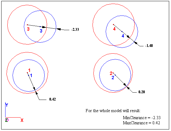
Min Clearance Mode: Min Clearance measures and displays the minimum value for the minimum clearance, obtained by comparing all the minimum clearance values of the "n" assemblies. In example below, the Min Clearance = -2.33
Max Clearance Mode: Max Clearance measures and displays the maximum value for the minimum clearance, obtained by comparing all the minimum clearance values of the "n" assemblies. in example below, the Max Clearance = 0.42
This measure may produce incorrect Contributor Analysis or GeoFactor Equation-Based results, see Analysis Comparison & Assumptions.
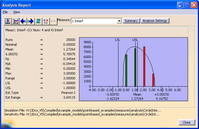
Interference Mode: For Interference mode, the histogram will have a number of bars, separated from each other and representing the number of failed assemblies. The bars can be positioned at 0, 1, 2, ..., n, where n is the maximum number of hole/pin assemblies. There is not necessary to have a bar for each number of assemblies. This means that the statistics created with Interference Mode may not be helpful in analyzing this measurement. The best method to analyze this data is to save the raw data to a help file and analyze it in a spread sheet.
The bar height for each number indicates how probable is to have interference for that number of assemblies, compared to the others.