The purpose of the
|
Inputs
Select the Contact move icon ![]() to get the Contact Move dialog box:
to get the Contact Move dialog box:
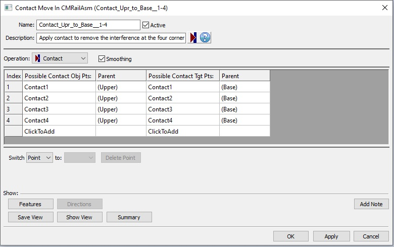
•Name: The move name must be unique to the model.
•Description: This is an optional explanation of what the move does.
•Help: The Help button is context sensitive; it will open the Help Manual at required topic page.
•Operation: Allows the user to select the appropriate operation for the move. The drop-down list lists: Clamp, UnClamp, Join, LockDOF, UnLockDOF, Contact, Un-contact and DefoMorphing.
•Activate Smoothing to deform the entire part.
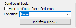
•Options:
1.When a measure is added in the Options as a Condition will trigger the move when the selected measure is within the specified limits.
2.When a measure is added in the Options as a Condition and the "Execute if out of specified limits" is checked will trigger the move when the selected measure is outside the specified limits.
•Possible Contact Obj Pts: These are the points selected on the object part. Each object point has a corresponding target point. The number of points can be from 1 to n.
•Possible Contact Tgt Pts: These are the points selected on the target part. The number of points can be from 1 to n and they should be matched with the object points.
Note: The interference check is performed along the target point's direction. Every point pair (object/target) may have a different direction.
•Click To Add: Allows the user to Add more contact points.
•Delete: Will delete the selected point.
•Switch: can be applied to a selected point or to the entire selected row that needs to be reordered.
Outputs
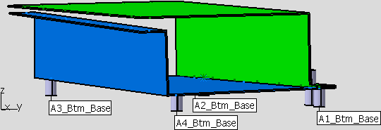
•The result of this routine will be zero interference between the object and target points listed. The assembly shown below is clamped at points A1_Btm_Base, A2_Btm_Base, A3_Btm_Base and A4_Btm_Base. The lower flange is also welded.
•A join is applied at the pair of points Wld_6 corner. The force pulls the flange and deforms the part from the original shape showing interference at points A3_Top_Upper. A gap measurement at the A3_Top_Upper in the z-direction shows a nominal value of -1.238 mm.
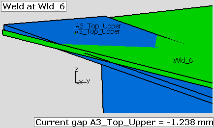
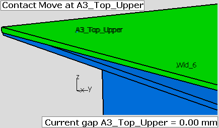
•A contact move is added for the points A3_Top_Upper. After nominal build, the gap current nominal value becomes 0.00 mm. The points line up in the z-direction. In most cases, the points will not line up in the x-direction or in the y-direction. This is expected because the parts are deformed along the target point vector, so most of the time the two points will not be coincident.
Process
•Select the Contact Move icon ![]() and choose the location for the Contact Move. This move must be at a product level, at least one level above the part. This move must be located after Load FEA Data move.
and choose the location for the Contact Move. This move must be at a product level, at least one level above the part. This move must be located after Load FEA Data move.
•Add or remove points using Click To Add option.
•Use the Features button to display the points on the screen and verify if their location is correct.
Validation Messages
•This message is removed from the Run Log: "ObjPt and TgtPt with the Same Direction at Contact TGT Points". The following message is added to the Log file: "A gap (based on Target point direction and Object-Target points position) presents at location...(
Reference
ASME Digital Library - Efficient Consideration of Contact in Compliant Assembly Variation Analysis
http://scitation.aip.org/getabs/servlet/GetabsServlet?prog=normal&id=JMSEFK000131000001011005000001&idtype=cvips&gifs=yes