The purpose of
|
Inputs
Select the Force icon ![]() to get the Force Move dialog box:
to get the Force Move dialog box:
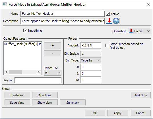
•Name: The move name must be unique to the model.
•Description: This is an optional explanation of what the move does.
•Help: The Help button is context sensitive; it will open the Help Manual at required topic page.
•Activate Smoothing to deform the entire part.
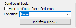
•Options:
1.When a measure is added in the Options as a Condition will trigger the move when the selected measure is within the specified limits.
2.When a measure is added in the Options as a Condition and the "Execute if out of specified limits" is checked will trigger the move when the selected measure is outside the specified limits.
•Object Features: These are the points where the force will be applied. The number of points can be from 1 to n.
•Amount: This is the force value applied to each point.
•Same Direction based on first object: If checked all points will use the first point's direction. If unchecked each point can vary along its own Associated Direction.
•Dir. Type: Sets the direction of deformation for Object points and it has the following options, similar to the direction options available in the other MTMs: Type In, Two Pt, Normal, AssocDir (picks up the associated direction of the Object point), and TwoPtDir.
Note: Check the CATIA settings for the measurement units used for the force.
Outputs
•The result of this routine will be the deformed part. The part shown below is positioned at points O1, O2, and O3. A force is applied at the forth corner. The force pulls the flange and deforms the part from the original shape (black contour) to the final shape (shown in orange).
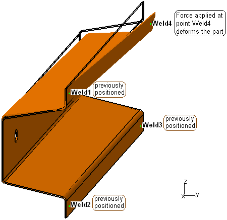
•Deformation propagates to other feature points on the part and to the parts connected to it.
Process
•Select the Force move icon ![]() and choose the location for the move to be created. This move must be at a product level, at least one level above the part.
and choose the location for the move to be created. This move must be at a product level, at least one level above the part.
•Add or Remove points using the plus ![]() and minus
and minus ![]() buttons.
buttons.
•Set the correct direction for each point if necessary.
•Use the Features button to display the points on the screen and verify if their location and direction are correct.