The purpose of the
|
Inputs
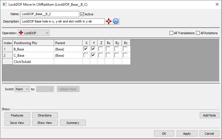
Select the Compliant LockDOF Move icon ![]() to get the LockDOF Move dialog box:
to get the LockDOF Move dialog box:

•Name: The move name must be unique to the model.
•Description: This is an optional explanation of what the move does.
•Help: The Help button is context sensitive; it will open the Help Manual at required topic page.
•Operation: Allows the user to select the appropriate operation for the move. The drop-down list displays: Clamp, UnClamp, Join, LockDOF, UnLockDOF, Contact and DefoMorphing.
•Positioning Pts: These are the points that will be set at current location. The number of points can be from 1 to n.
•Parent: Lists the fixed points' part(s).
•X, Y, Z: These are the directions along which the points will be constrained. These three directions are the components of the Nominal Build vectors for each point. The default will be "checked" boxes for all three directions X, Y, Z.
•Rx, Ry, Rz: Constrained rotations, when checked. The rotations are off by default.
•Click To Add: Allows the user to Add more locked points.
•Delete Point: Will delete the selected point.
•Switch: can be applied to a selected point or to the entire selected row that needs to be to be reordered. When switching the entire row the locked features are switched along with the point.
•Direction: Displays the point direction in the Graphics.
Outputs
•The result of this routine will be a part whose deformation is restricted at the specified constrained points.
Process
•Select the LockDOF Move Icon ![]() and choose the location for the LockDOF Move. This move must be located after Initialization Move.
and choose the location for the LockDOF Move. This move must be located after Initialization Move.
•Add or remove points using Click To Add option.
•Activate the desired boxes to constrain translations and/or rotations.
•Use the Show Features button to display the points and the directions along which the points are fixed, on the screen.
Notes
•LockDOF Move with 3DOF matrix for a solid mesh will not constrain rotations; they are controlled by the mesh itself. In this case the locked features should form a plane instead of a line to avoid an under-constrained situation.
• You can apply a LockDOF after a Clamp. If you lock a clamped point it will overwrite the clamp.