The purpose of the
|
Inputs
Select the Join icon ![]() to get the Join Move dialog box:
to get the Join Move dialog box:
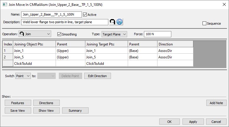
•Name: The move name must be unique to the model.
•Description: This is an optional explanation of what the move does.
•Help: The Help button is context sensitive; it will open the Help Manual at required topic page.
•Operation: Allows the user to select the appropriate operation for the move. The drop-down list lists: Clamp, UnClamp, Join, LockDOF, UnLockDOF, Contact, Un-contact and DefoMorphing.
•Activate Smoothing to deform the entire part.
•Joining Type: Target Plane, Coincident, or Tie. See Joining Type Mode for options.
•Force: Allows adding a joining force value. Sometimes this value is insufficient to completely close the gap between points. In this case the move will not be executed (part nodes are return to the location they were in, prior to the failed move), and reported as a failed assembly in the Run Log along with the necessary force value to completely close the gap.
▪Infinite force - this option will apply as much force as it is necessary to close the gap. This is the default.
•Allowable Gap: the distance between target and object at the joining points, set by the user. If this distance is met the join move is executed, otherwise the move is ignored and a message specifying the required force is issued in the Run Log.
•Sequence: When checked this option calculates the results for each pair one at the time in the order they are listed in the move. The assembly will deform after each pair, similar to having individual join moves. If left unchecked the calculation is done for all pairs and the deformation is applied for the entire move.
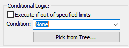
•Options:
1.When a measure is added in the Options as a Condition will trigger the move when the selected measure is within the specified limits.
2.When a measure is added in the Options as a Condition and the "Execute if out of specified limits" is checked will trigger the move when the selected measure is outside the specified limits.
•Join Object Pts: These are the object points that will be joined to the target. The number of points can be from 1 to n.
•Join Target Pts: These are the target points that will be joined to the object. The number of points must be the same as the number of object points and they should be paired.
• Edit Direction: Sets the direction of deformation for Object points and it has the following options, similar to the direction options available in the other MTMs: Type In, Two Pt, Normal, AssocDir (picks up the associated direction of the Target point), and TwoPtDir.
•Click To Add: Allows the user to Add more joining points.
•Switch: can be applied to a selected point or to the entire selected row that needs to be to be reordered.
Outputs
•The result of this routine will be the deformed object and target parts (compliant object points to rigid target points/plane)
•Deformation propagates to other feature points on the object component as well as other previously joined parts.
Process
•Select the Join Icon ![]() and choose the location for the Join move. This move must be at a product level, at least one level above the part, after the Load FEA move.
and choose the location for the Join move. This move must be at a product level, at least one level above the part, after the Load FEA move.
•Add object/target points using the Click To Add option.
•Set the correct direction for each pair if necessary.
•Use the Show: Feature button to display the points on the screen to verify the object points correspond with their respective target points.
Notes:
•The join process will propagate deformation between the two parts being attached to each other. It also combines the stiffness matrices from the two parts into a new stiffness matrix. At this point, any further action done on these parts as far as additional clamping/unclamping/Joining will see the effects of a single stiffness matrix.
•Target points' vectors are displayed along with the features when Show: Features button is used in the Join move dialog box.