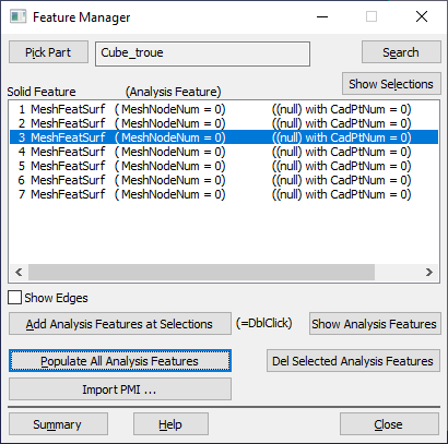
The Feature Manager function shows all possible surfaces of a part and allows the user to create a Feature linked to a surface on a part. It works similar to creating Feature Points or when creating GD&T by selecting a surface.
Users can use this function to either create or delete 3DCS Features and edges of a part. Deleting a feature may change other functions, such as MTMs or GD&T. This dialog doesn't display what features are linked to. It will display the name of feature, if the feature was renamed in the model.
|
Procedure:
Open the Feature Manager dialog from Geometry tab:
1.Select a part in the model by using [Pick Part]. Search for a part by using the [Search] function.
2.If any surfaces were created from other methods (MTMs, GD&T, Feature Point), they will be shown in the list. Otherwise, double-click on a MeshFeatureSurf to create a new Feature in 3DCS, or select a surface and select the [Add Analysis Features at Selection] button.
a.Selecting Show Edges will list all the edges on the part. To create an edge, double-click a line for an edge.

Commands:
•Pick Part: Allows the user to select a part from Navigation Window.
•Search: Allows the user to search part by name.
•Show Selections: Shows the current selected solid features (mesh surface).
•Add Analysis Features at Selections: Will create Features to the selected surface. Use Shift or Ctrl keys to select multiple surface.
oNote: Double-clicking an individual Solid Feature will create an Analysis Feature.
•Show Analysis Features: Will show the new created Analysis Features.
•Populate All Analysis Features: Will add mesh nodes to all Analysis Features created.
•Delete Selected Analysis Features: Will remove the Analysis Feature.
•Import PMI: Using the DCS Converter or importing CAD geometry into 3DCS may also have GD&T in the part. 3DCS will create a pmi.xml file with GD&T information. This function allows the user to import the GD&T if deleted or no GD&T was created. No other requirements; this will also create Features linked to the CAD.
•Close: Will close the dialog.
•Help: Opens the Help Manual at the Feature Manager page.
•Summary: will open a dcs_featmgr_sum.tmp file (using Notepad), and list all parameters for the Feature Manager dialog. Select File/Save As to save the data in text format.
Notes:Solid Feature: The solid part or surface of the selected part. Default name = MeshFeatSurf. Other names that are used in the Help Manual or the Community: CAD surface. Analysis Feature: A 3DCS surface. If no feature has been created 3DCS, "(MeshNodeNum = 0)". If a feature is defined in 3DCS, the node number will update to show the amount of nodes on the surface "(MeshNodeNum=27)". (Null): References the name of the CadSurf used in 3DCS. If the user changes the name, it will be shown here. CadPtNum: This will update to show the amount of points and mesh nodes available on the surface. If the MeshNodeNum = 27 and the user creates 5 Feature Points, the CadPtNum will show a total of 32 "(CadPtNum = 32)".
|