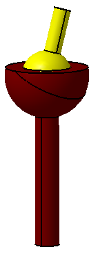
The ![]() Spherical Joint (also called a ball joint or spherical bearing) locates two centers to one another, controlling three translation DoF's. The object part in this assembly is free to rotate about its center in any direction. The object can not translate in any direction. Some example applications of this joint include a ball point pen, a trailer hitch, or as a pivot between wheels and suspension on a car.
Spherical Joint (also called a ball joint or spherical bearing) locates two centers to one another, controlling three translation DoF's. The object part in this assembly is free to rotate about its center in any direction. The object can not translate in any direction. Some example applications of this joint include a ball point pen, a trailer hitch, or as a pivot between wheels and suspension on a car.
Feature Specification
Object and target features can be any of the following combinations.
Object Features Target Features
One spherical feature or One spherical feature or
One point to define a center One point to define a center
Procedure
The spherical joint can be created for a variety of model applications, but the basic procedure is as follows.
STEP 1 Feature Tab:
Click in the Object Features box and select one feature from the part(s) to be moved.
Click in the Target Features box and select one corresponding feature of the target part(s).
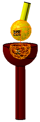
An example is shown below where the spheres of rotation are Features.
STEP 2 Move Parts Tab:
Parts should automatically be added to Move Parts based on the Tree structure of the model. Verify that these are the desired parts. Only two parts can be added to this list. The first part corresponds to the Object features and the second part corresponds to the Target features.
STEP 3 Settings Tab:
Update settings as desired.
STEP 4 Floating Tab:
Turn float on/off by checking the box after selecting the hole-pin pair from the drop-down list (if applicable). Note that float can only be applied in two of three directions that the move controls.
Also See