The
|
Feature Specification
Object and target features can be any of the following combinations.
Object Features |
Target Features |
One feature to define a plane |
One feature to define a plane |
Two features to define a slot/tab center plane |
Two features to define a slot/tab center plane |
One point to define a plane |
N'th amount of Features to define a plane |
Procedure
The planar joint can be created for a variety of model applications, but the basic procedure is as follows
1.Feature Tab:
Click in the Object Features box and select one or two features from the part(s) to be moved.
Click in the Target Features box and select one or two corresponding feature(s) of the target part(s).
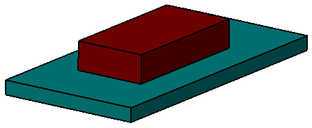
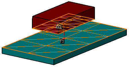
An example is shown below where the touching plane surfaces are the Features.
STEP 2 Move Parts Tab:
Parts should automatically be added to Move Parts based on the Tree structure of the model. Verify that these are the desired parts. Only two parts can be added to this list. The first part corresponds to the Object features and the second part corresponds to the Target features.
STEP 3 Settings Tab:
Update settings as desired.
STEP 4 Floating Tab:
Turn float on/off by checking the box after selecting the slot-tab pair from the drop-down list (if applicable).
Also See