The ![]() Universal Joint (also called universal coupling, U-joint, Cardan joint, Hardy-Spicer joint, or Hooke's joint)attaches two parts at the ends of a pair of axes. This move is a simple version of a Univeral joint and does not transmit rotation. Some example applications of this joint include a sailboat tiller or a car's driveshaft.
Universal Joint (also called universal coupling, U-joint, Cardan joint, Hardy-Spicer joint, or Hooke's joint)attaches two parts at the ends of a pair of axes. This move is a simple version of a Univeral joint and does not transmit rotation. Some example applications of this joint include a sailboat tiller or a car's driveshaft.

Feature Specification
Object and target features can be any of the following combinations.
Object Features Target Features
Axis of a cylinder or Axis of a cylinder or
Line segments or Line segments or
Points that represent lines Points that represent lines
Procedure
The universal joint can be modeled by completing the following procedure.
STEP 1 Feature Tab:
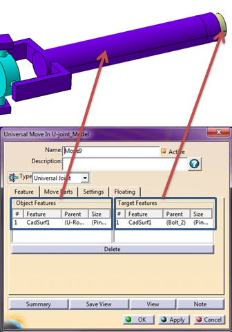
Click in the white box of Object Features and select the axis of the outer rotating part in the graphics window.
Click in the white box of Target Features and select the axis of the inner part in the graphics window.
See example below.

STEP 2 Move Parts Tab:
Parts should automatically be added to Move Parts based on the Tree structure of the model. Verify that these are the desired parts. Only two parts can be added to this list. The first part corresponds to the Object features and the second part corresponds to the Target features.
STEP 3 Settings Tab:
Update settings as desired.
STEP 4 Floating Tab:
Floating can be turned on and off with check box before hole-pin pair.
Also See