The
See Also: Common Parameters
|
Procedure:
The Kinematic Motion move allows the user to translate or rotate parts while maintaining defined constraints and joints to model the motion of an assembly. The motion definition can be modified based on cycle parameters.
1.Motion Tab: Choose the Motion Type from the drop-down list. Based on whether the 'Comp' or 'By Steps' method is chosen, specify the start/end point of motion and the step size or the values to step the motion to.
2.Feature Tab: Click in the white box of Center of Rotation and select the feature or axis about which the assembly will be rotated. If Motion is set to Translate component or Translate by steps, this field will not be available as it is not needed. Click in the white box of Direction and select a feature or axis about which the assembly will rotate in the graphics window (it can be the same as the other field.) If translating parts, select a feature or axis about which the assembly will translate along.
For example, the end of the crankshaft was chosen as both the Center of Rotation and Direction below.
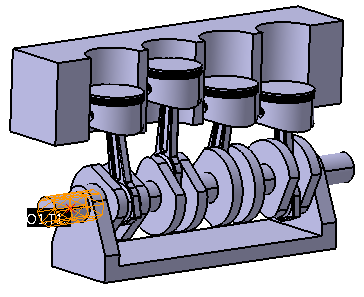
3.Move Parts Tab: Select the part or parts that will be moved the exact amount specified by the motion. In the engine above, only the crankshaft should be selected. The other moves will cause the rods and pistons to move with it. If a second part is listed, then the first part will be moved relative to the second part. This allows both parts to be moved later as a rigid sub-assembly.
The Kinematic Motion move allows the user to translate or rotate parts while maintaining defined constraints and joints to model the motion of an assembly. The motion definition can be modified based on cycle parameters.
1.Motion Tab: Choose the Motion Type from the drop-down list. Based on whether the 'Comp' or 'By Steps' method is chosen, specify the start/end point of motion and the step size or the values to step the motion to. 2.Feature Tab: Click in the white box of Center of Rotation and select the feature or axis about which the assembly will be rotated. If Motion is set to Translate component or Translate by steps, this field will not be available as it is not needed. Click in the white box of Direction and select a feature or axis about which the assembly will rotate in the graphics window (it can be the same as the other field.) If translating parts, select a feature or axis about which the assembly will translate along.
For example, the end of the crankshaft was chosen as both the Center of Rotation and Direction below.
3.Move Parts Tab: Select the part or parts that will be moved the exact amount specified by the motion. In the engine above, only the crankshaft should be selected. The other moves will cause the rods and pistons to move with it. If a second part is listed, then the first part will be moved relative to the second part. This allows both parts to be moved later as a rigid sub-assembly. |
|---|
Parameters:
The steps of the motion are specified in this tab. First, choose a type of motion out of the four different actions specified in the drop-down list. Depending on the type of move, the user can specify and start and end position of the assembly and how many steps the motion is divided into.
Motion Type:
•Translate Comp: Translates the parts in the list in the Move Parts tab along the direction of the feature in the Direction field in the Feature tab.
•Rotate Comp (Deg): rotates the parts in the list in the Move Parts tab around the axis defined by the features in the Center of Rotation and Direction fields in the Feature tab.
•Translate By Steps: translates the parts in the list in the Move Parts tab along the direction of the feature in the Direction field in the Feature tab.
•Rotate By Steps (Deg): rotates the parts in the list in the Move Parts tab around the axis defined by the features in the Center of Rotation and Direction fields in the Feature tab.
Motion Steps: The number of steps the translation or rotation will be divided into.
Motion Beg Pos: With "Comp" motion types, this is the first value stepped to. Model Nominal Position will build the model to Motion Move's Beg_Pos.
Motion End Pos: With "Comp" motion types, this is the last value stepped to.
Defined Motion Steps: With "By Steps" motion types, add the values to be stepped to from this list.
Notes:•When running a Simulation, the Simulation will only build the Motion to one step get results from Tolerances/GD&T. Alternatively, the user can utilize the Design of Experiments user-dll (dcu_DOE_form.dll) to get results for each Motion Step set in the Motion Move. The user can add the StatRow, Raw Data, Monte Carlo Simulation, Sensitivity and GeoFactor results for each step.
|