Parts are often located using Pin/Hole and Pin/Slot combinations. If a pin is not self-centering, then the clearance between the sizes of the pin and hole is a source of variation. Think about a large hole with a small pin. The pin is free to move within the hole until it contacts the side. The larger the clearance, the more variation in the assembly. In 3DCS, the pin and hole clearance is called "floating" and needs to be included in the model. A Pin located inside of a Hole will control a part in 4 directions. Thus, it is known as a "4-way" locator. For this terminology, a direction and its opposing direction are counted as two separate directions, for example +X and -X. In the context of degrees of freedom, they are counted as one degree. A Pin located inside of a Slot will control a part in 2 directions. Thus, it is known as a "2-way" locator.
First, we will look at the floating between the Headlamp and Bracket.
•Double-click the Headlamp-to-Bracket Move in the tree to open the Six-Plane Move dialog.
•Click the [Options] button. This will open the Move Options dialog.
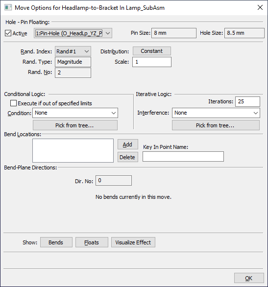
The Move Options dialog is used for controlling Hole-Pin floating, Conditional Logic, Iterative Logic, and Bending. Only floating is covered in this tutorial. The other functions are for advanced modeling.
•Verify the Active box is checked for the first Pin-Hole pair, the pin point O_HeadLp_YZ_Pt in the Headlamp to the hole point T_HeadLp_YZ_Pt in the Bracket.
The Active box controls if the floating will be included in the move. If the floating is active, the clearance between the hole and pin will be included as a source of variation. If the floating is not active, the centers of the pin and hole will be aligned (in the direction they control) regardless of the clearance. If you cannot activate the floating or do not have an option for floating, go back to the move and verify it was created correctly.
•Set the Rand. Index to Rand#1 and verify the Distribution is set to Constant.
•Set the Rand. Index to Rand#2 and verify the Distribution is set to Uniform with a Range of 360deg and Offset of 0deg.
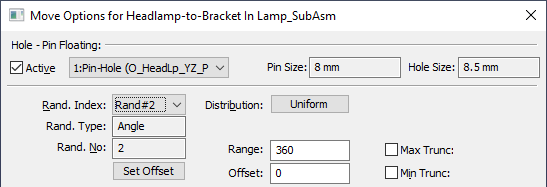
The indexes Rand#1 and Rand#2 are similar to radial coordinates. Rand#1 controls the magnitude of the offset between the hole and pin centers. Rand#2 controls the angular direction of the offset between the hole and pin. With Rand#1 set to Constant, the pin will always contact the edge of the hole. With Rand#2 set to Uniform and a Range of 360deg, there is equal probability of the pin floating in any direction.
•Select the second Pin-Slot pair (the pin point O_HeadLp_Z_Pt in the Headlamp to the slot T_HeadLp_Z in the Bracket) from the drop-down list.
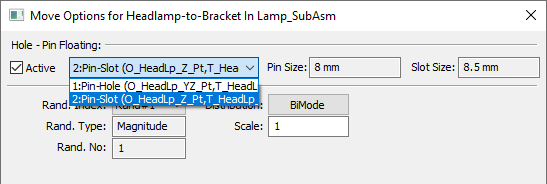
•Verify the Active box is checked for the second Pin-Slot pair.
•Set the Rand. Index to Rand#1 and verify the Distribution is set to BiMode.
Because a Pin-Slot pair is a 2-way locator, there is only one direction to control and only one Rand. Index, the magnitude. BiMode will cause the pin to float to contact either wall of the slot.
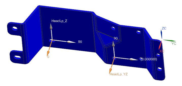
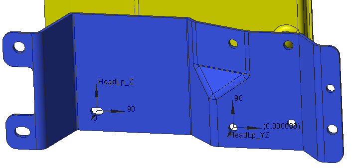
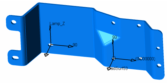
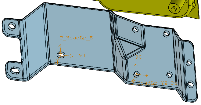
•Click [Floats] near the bottom of the Move Options dialog. This will display the directions of the floats for the Headlamp-to-Bracket Move in the graphics.Note: 3DCS does not show its features through the Solidworks geometry. To see any 3DCS data that would otherwise be within a Solidworks part, you must change the transparency setting of the Solidworks part.
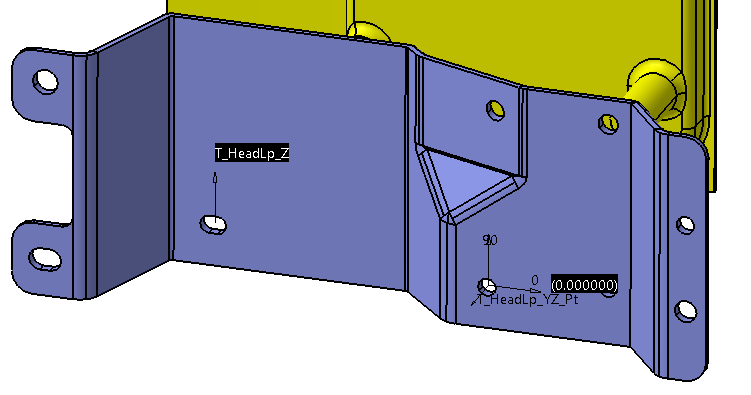
•Click [Close] in the Show...Display dialog.
•Click [OK] in the Move Options dialog.
•Click [OK] in the Six-Plane Move dialog.
Next, we will look at the floating between the Turnlamp and Bracket.
•Double-click the Turnlamp-to-Bracket Move in the tree to open the Step-Plane Move dialog.
•Click the [Options] button. This will open the Move Options dialog.
•Verify the Active box is checked for the first Pin-Hole pair, the pin point O_TurnLp_YZ_Pt in the Turnlamp to the hole point T_TurnLp_YZ_Pt in the Bracket.
Similar to the floating between the Headlamp and Bracket, the first Pin-Hole pair is a 4-way locator between the Turnlamp and Bracket. So we will keep the default Constant and Uniform distributions.
•Set the Rand. Index to Rand#1 and verify the Distribution is set to Constant.
•Set the Rand. Index to Rand#2 and verify the Distribution is set to Uniform with a Range of 360deg and Offset of 0deg.
The second Pin-Hole pair between the Turnlamp and Bracket is acting like a 2-way locator so we will set the floating to simulate a pin and slot combination.
•Select the second Pin-Hole pair (the pin O_TurnLp_Y_Pt in the Turnlamp to the hole T_TurnLp_Y_Pt in the Bracket) from the drop-down list.
•Verify the Active box is checked for the second Pin-Hole pair.
•Set the Rand. Index to Rand#1 and set the Distribution to BiMode.

•Set the Rand. Index to Rand#2.
•Click [Set Offset]. This will open the Pick Vector dialog.
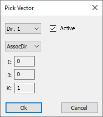
•Set the method to Type In in the drop-down list then enter (0, -1, 1) for the vector.
•Click [OK].
This will automatically change the Distribution to Constant and set the Offset angle. Changing the Offset sets the direction of the simulated slot. Your dialog should look similar to the image below.
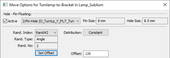
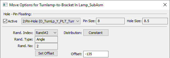
•Click [Floats]. This will display the directions of the floats of the Turnlamp-to-Bracket move in the Graphics Window.
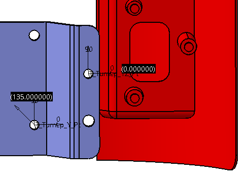
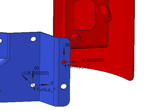
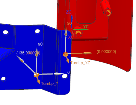
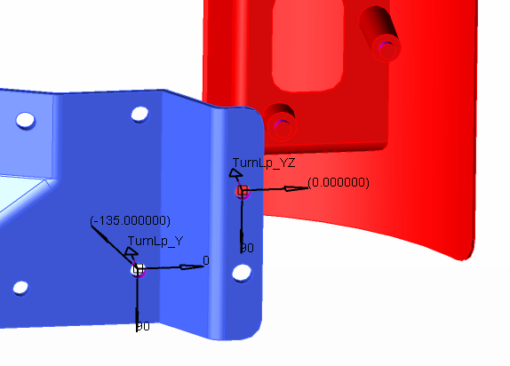
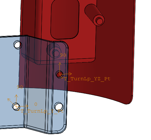
•Click [Close] in the Display dialog.
•Click [OK] in the Move Options dialog.
•Click [OK] in the Step-Plane Move dialog.
Even without tolerances adding variation to the nominal geometry of the parts, we have variation in the assembly due to the clearances between holes and pins.
•Click the ![]() Nominal Build button.
Nominal Build button.
•Click the ![]() Deviate button. The parts will vary due to the floating.
Deviate button. The parts will vary due to the floating.
•Click [Close] in the Deviate dialog.
•Click ![]() Separate.
Separate.
•Save the model.