The
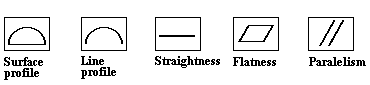
Some of the feature control frames that can be represented by linear tolerance are:
Within this section:Inputs Methodology Modes Directions Multiple Scales
|
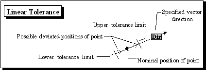
Input:
Distribution: Required
Magnitude: All parameters required
Name: Required
Direction: Required
Features: Required
Description: Optional
Modes:
The mode field lets you specify different combinations of magnitude and direction for greater flexibility. The mode option has four choices: Individual, Group, and Composite.
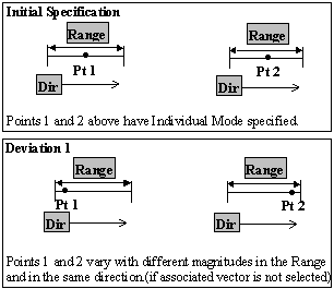
Individual:
When Individual Mode is specified, each point in the list that is associated with the tolerance varies:
•With different magnitudes in the specified range.
•In the direction specified for each point.
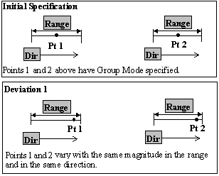
Group:
When Group Mode is specified, each point in the point list box that is associated with the tolerance varies:
•With the same magnitude in the specified range.
•In the same direction (if associated vector is not selected.)
Composite:
Composite Mode is used when a Composite Feature Control Frame is specified.
•The range values are the same as the tolerance values from the feature control frame.
•Normal distributions are required (except for worst case analysis.)
•Any Offset should be applied to only one of Random Number index.
|
|
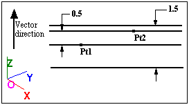
NOTE: For Rand#1 the Range = 1.5 For Rand#2 the Range = 0.5, as is shown in the feature control frame for this tolerance:
•When running the simulation in 3DCS, the tolerance values are RSSed (unless the distributions are set to Modal, BiMode, Step, Constant, or UserDef. For these distributions, the ranges are subtracted to support worst case analysis.) The reason we RSS the values is because the number of features on which the tolerance applies varies from one GD&T callout to another.
Direction methods: Specify the Vector direction for each point in the tolerance. See: Vector Directions
Multiple Directions: With more than one point, the user can specify each point to have a different direction. Each direction can be specified with any method available in the Direction Method list (shown below).
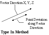
Type In Method: Specify the vector's ( I, J, K) values. The tolerance is applied along the vector's direction.
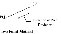
Two Points Method: Varies a point along the vector of the line segment chosen. Select a line segment (2 points) along which the tolerance is applied.
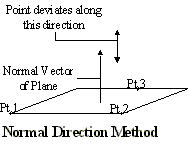
Normal Direction Method: Varies a point in the direction of the vector that is normal to the selected plane. Select 3 points to specify the plane along whose vector the tolerance is applied.
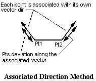
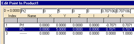
Associated Direction Method: Associates a vector direction to each point from the "point dialog box".
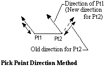
Pick Point Direction Method: Associates the same direction to all points. The direction will be the one chosen (ex. direction of Pt 1).
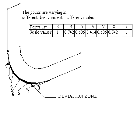
Multiple Scale: Multiple Scale varies each point in the point list that is associated with the tolerance:
•In different directions, if desired.
•With different scale values. To specify the Scale for each feature, select a specific Feature in the list and change the scale value. Scale default is set to 1.
The Scale value will be applied to both the Range and Offset. |
Notes:If multiple tolerances are on the same feature (i.e.: Composite), you cannot have the same Truncation value for each frame in RSS mode. The Truncation is independent for each frame, so the total variation could exceed the location truncation.
|