Directions are used in Moves, Tolerances, and Measures (MTMs.) They define how the point will deviate from a tolerance; what direction a measurement will measure features or points; will fix or control the degree of freedom based on the feature or point direction.
Direction Methods:There are six different types of directions used in 3DCS. Two Point, Normal direction, Associative direction, and Auto direction are dynamic and will update with every build; Type-In is static. Point Point direction is a constant direction. Within this section:
|
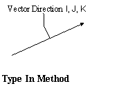
 Type In
Makes the I, J and K components of the vector direction available to edit the values in the appropriate boxes to define the vector direction. The vector is automatically normalized. •A Type-In vector is relative to the Local Coordinate System (LCS) of the part containing the MTM it is used in. If the part is rotated, the direction of the vector will rotate with the part, although the displayed vector will not change. (All other vectors are displayed relative to the Global Coordinate System (GCS)). •Always check to verify if the vector is correct.
|
|---|
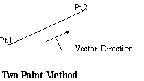
 Two Point
Two Point direction allows the user to use two points as a direction. Click on Pick Dir Pts and select two points. The two point direction calculates a vector parallel to a line formed by the two points. The vector values are displayed relative to the Global Coordinate System (GCS.)
|
|---|
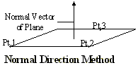
 Normal Direction
Similar to Two Point, Normal requires three points, or a plane, to define a direction. Click on Pick Dir Pts and select three points. The normal direction calculates a vector normal to the plane defined by the three points. The vector values are displayed relative to the Global Coordinate System (GCS.)
|
|---|
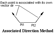
 Associated Direction
Each point and feature in the model has a direction associated with it. The associated direction uses the direction from the associated point or feature in the MTM for each direction. Even if there is only one direction in the MTM, if the points or features have different directions, the MTM will use separate directions for each point or feature. The vector values are displayed relative to the Global Coordinate System (GCS.)
|
|---|
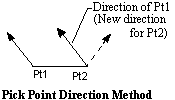
 Pick Point Direction
Similar to Normal and Two Points, Pick Point only requires one point. Click on Pick Dir Pts and select one point. Pick point direction uses the direction associated with the point or feature selected. The vector values are displayed relative to the Global Coordinate System (GCS.)
|
|---|
 Auto
Auto
The automatic direction uses a different calculation method for each MTM. The vector values are displayed relative to the Global Coordinate System (GCS). Auto direction can be used for all directions in the move. •If used for the Primary plane direction, it calculates the vector normal to the three Primary points. •If Auto is selected as a Secondary direction in a Step Plane move, it uses the direction normal to the first direction and normal to the line between the fourth and fifth target points. •If Auto is selected as a Secondary direction in a Six Plane move, it uses the direction normal to the average of the first three directions and normal to the line between the fourth and fifth target points. •If Auto is selected as a Tertiary direction in a Step Plane move, it uses the direction normal to the first direction and normal to the second direction •If Auto is selected as the tertiary direction in a Six Plane move, it uses the direction normal to the average of the first three directions and normal to the average of the fourth and fifth directions.
|
|---|
