|
|
In this section:Procedure |
|
Procedure:
1.In a new model, create the necessary points or features to define a Six-Plane or a Step-Plane move. The user can create multiple moves with the same locators.
2.Launch the ![]() Locator Sensitivity Analyzer
Locator Sensitivity Analyzer
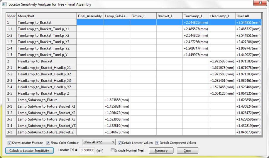
LSA will generate a table showing the maximum part deviation for each move. The maximum part deviation is the maximum of all the deviations calculated at each point and mesh node in the part. The deviation of each point and mesh node in each target part is measured along the X, Y, and Z directions while the target features are deviated.
Locator Tol ±: The amount the target features are deviated along the X, Y, and Z directions.
Calculate Locator Sensitivity: Press this button after Nominal Build to run the analysis with the selected options.
Show Locator Feature: Labels the target features from a selected row in the table.
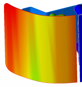
Show Color Contour: Adds color contour to each part representing the selected part deviation from the table according to the Color Contour options set.
Show… (dropdown list): When set to X, Y, or Z only, it shows the maximum part deviation projected along a vector. When set to Show All-XYZ, it shows the maximum combined effect of the three deviations.
Detail: Locator Values: Shows the part deviation from each target feature. When unchecked, only the maximum deviation from all the target points in each move is shown.
Detail: Component Values: Shows the part deviation for each part. When unchecked, only the maximum deviation is shown.
Include Nominal Mesh: When unchecked, the part deviation is only calculated at existing points and feature mesh. When checked, the part deviation is also checked on all the part surfaces (using the CGR or HSF file.) Please note this option could cause the analysis to take considerable time.
![]()
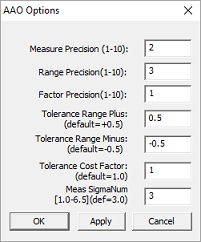
Options menu - Allows setting the default values for measure, tolerance and factor (coefficient) decimals.
|
•Measure Precision: Changes the decimal place value for Measures, across the top of the GeoFactor Analyzer, SBS and CTI dialogs. •Range Precision: Changes the decimal place value for the Tolerance Range value for GeoFactor Analyzer, Simulation Based Sensitvity (SBS), Critical Tolerance Identifier (CTI), Tolerance Optimizer, LSA dialogs. •Factor Precision: Changes the decimal place value of the Factors or overall display of the GeoFactor Analyzer dialog. •Tolerance Range (Plus/Minus): Applies to the Critical Tolerance Identifier (CTI) dialog, changing the affective tolerance range for the Target 6-Sigma. •Tolerance Cost Factor: Changes the Cost Factor value in the Critical Tolerance Identifier dialog. •Measure Sigma Num: Changes the Sigma value for Measures in GeoFactor Analyzer, Simulation Based Sensitivity, |