3DCS models can use either points or features. There are two main types of points: Feature Points and Coordinate Points.
Feature Points are modeling points associated to a particular feature on a part. This feature is typically a surface, a pin, or a hole. Feature points have a "U" and "V" value which defines their relative location on the surface. The direction of a Feature Point is normal to the surface. If the point is at the center of a hole or pin, the direction of the point will be along the axis. The user can not directly edit the X,Y,Z coordinates and I,J,K direction of Feature Points. Because they are associated to a feature on a part, Feature Points will vary with any tolerance applied to the surface.
Coordinate Points are modeling points located within a part but not associated to a feature. The user can edit the X,Y,Z coordinates and I,J,K vector direction of Coordinate Points. Additionally, a circle diameter and circle type (pin or hole) can be specified for any Coordinate Point. Coordinate Points must be toleranced directly as they are not associated with any features of the part.
When creating points in this tutorial, always select the CAD surface, never the CAD edge (the line between two surfaces). Points created on the CAD edge will not be interpreted correctly by the software and can cause problems in the model. In this lesson, you will learn how to create Feature Points on the Headlamp and Turnlamp and Coordinate Points on the Bracket. These points are needed later on for the Moves and Measures.
For this tutorial, we will save a separate file for each lesson. This way, you can always go back to a previous lesson if necessary.
•With the Analyst_Tutorial_Lesson2 tab open, Go to the North quadrant of the Compass (called My Social and Collaborative Apps) and select the Collaborative Lifecycle app.
•Select the Analyst_Tutorial_Lesson2 Simulation and select ![]() Duplicate from the toolbar at the bottom.
Duplicate from the toolbar at the bottom.
•Right-click on the new duplicated Analyst_Tutorial_Lesson2 Simulation in the model tree and select Properties.
•In the Reference tab of the Properties dialog, change the Title to "Analyst_Tutorial_Lesson3".
•In the Compass, go to the South Quadrant (called My Content and Simulation Apps) and select 3DCS Variation Analyst V6 in the V+R My Simulation Apps section to return to the 3DCS Variation Analyst workbench.
•Go to File ![]() Save Management.
Save Management.
•Select the Lesson2.CATProduct and select [Save As...].
•In the Save As dialog, rename the Product to "Lesson3.CATProduct" and click [Save].
•In the Save Management dialog select [OK] to save the CATIA Product under its new name. The model is not actually saved until you click OK.
•Click the ![]() Application Button then select
Application Button then select ![]() Save As.
Save As.
•Change the File Name to "Lesson3.wtx".
•Click [Save] in the Save As dialog.
•Go to the Home tab if not already there.
•Go to File ![]() Save As.
Save As.
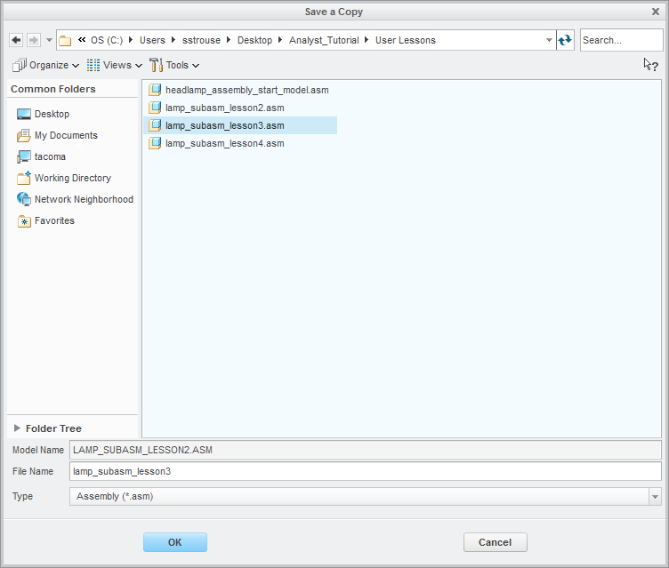
•In the Save a Copy dialog, enter "Lamp_SubAsm_Lesson3" for the File Name, make sure the Type is set to Assembly (*.asm), then click [OK].

•In the Assembly Save a Copy dialog, click [Save Copy and Open] to save the assembly under its new name, and open the newly saved assembly.
•Close the 3DCS Model Navigator and Creo window for Lamp_SubAsm_Lesson2.
•Click ![]() Update Model in the new window for Lamp_SubAsm_Lesson3.
Update Model in the new window for Lamp_SubAsm_Lesson3.
•Go to File ![]() Save As.
Save As.
•In the Save As dialog, enter "Lamp_SubAsm_Lesson3" as the new File name and make sure the type is set to Part Files (*.prt).
•Click [OK] in the Save As dialog.
Note the assembly name in the 3DCS Model Navigator is still "Lamp_SubAsm_Lesson2".
•Click ![]() Update Model. The assembly name will update to match NX.
Update Model. The assembly name will update to match NX.
•Go to File ![]() Save As.
Save As.
•In the Save As dialog, enter "Lamp_SubAsm_Lesson3" for the File Name, make sure the Type is set to Assembly.
•Select [Save] in the Save As dialog.
Note the assembly name in the 3DCS Model Navigator is still "Lamp_SubAsm_Lesson2".
•Click ![]() Update Model. The assembly name will update to match Solidworks.
Update Model. The assembly name will update to match Solidworks.