•Make sure ![]() Show Points is on so that the points will be shown in the Graphics Window as they are created.
Show Points is on so that the points will be shown in the Graphics Window as they are created.
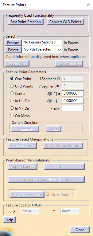
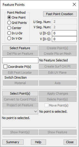
•Click the ![]() Feature Points button. This will open the Feature Points dialog.
Feature Points button. This will open the Feature Points dialog.
•Click [Fast Point Creation]. This will open the Fast Point Creation dialog.
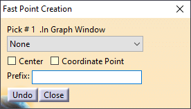
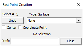
Fast Point Creation allows the user to create Feature Points, Coordinate Points or Circle Center Points. While the Fast Point Creation dialog is open, a point will be created on any surface, hole, or pin that is clicked. Multiple points can be created in a row. If you make a mistake when creating Fast Points, click [Undo] to remove the last point.
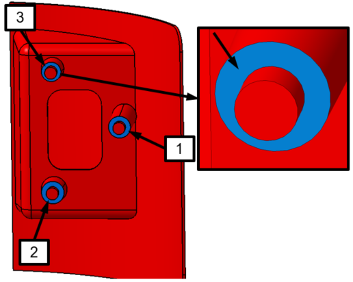
•With the Fast Point Creation dialog open, click each of the three surfaces highlighted in the Turnlamp in the figure below to create a point on each surface. Select the flat surface on each leg. It is best to spread the points as far as possible from one another to most accurately represent the interaction of the parts during the moves that will be created later.
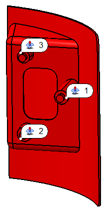
You should have three points in the Turnlamp similar to the image below. Your point numbers may be different depending on the order you selected the surfaces.
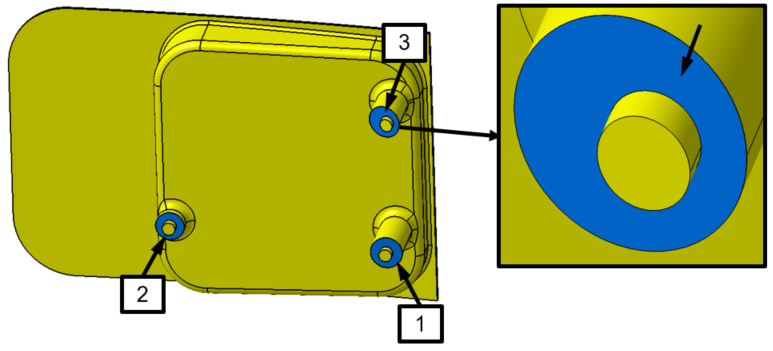
•With the Fast Point Creation dialog still open, click each of the three surfaces highlighted in the Headlamp in the figure below to create a fast point on each surface.
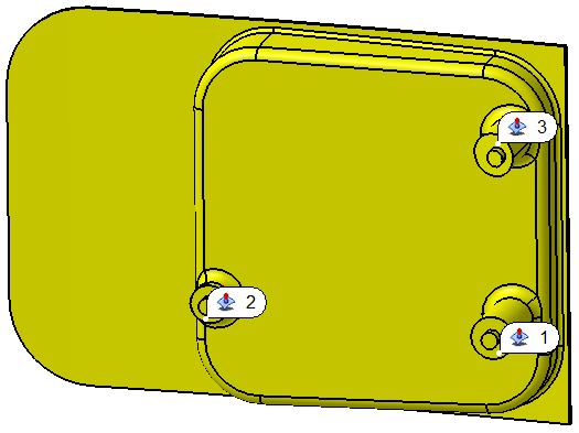
You should have three points in the Headlamp similar to the image below. Your point numbers may be different depending on the order you selected the surfaces.
•Click [Close] in the Fast Point Creation dialog.
We would also like to create points at the center of the pins that will be used to move the Turnlamp and Headlamp to the Bracket.
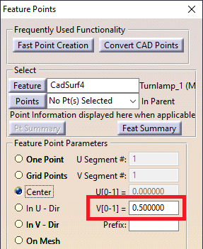
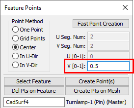
•In the Feature Points dialog, select Center in the Feature Point Parameters Point Method section of the dialog to begin creating a point at the center of the feature.
•Select [Feature] in the Feature Points dialog to enter the Pick Feat dialog.
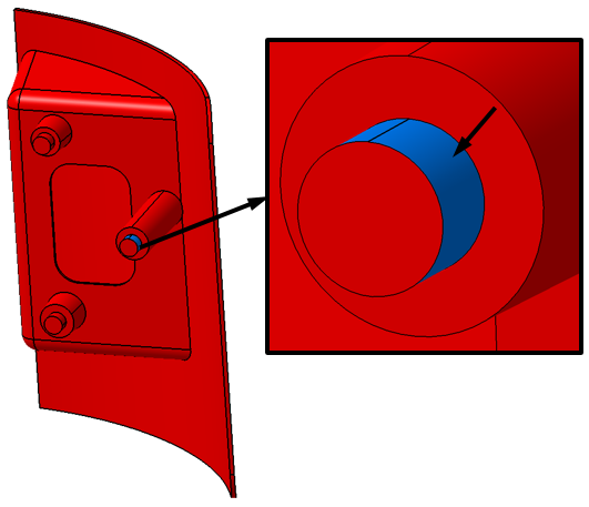
•Select either half (if the pin is not viewed as one continuous cylindrical feature from the CAD geometry) of the pin shown in the image below.
•Set the V value in the Feature Points dialog to "0.5" to put the point at the midpoint along the axis of the pin.
•Select [Create Point(s)] to create the center point.
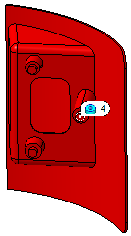
•Repeat the previous steps to create point 5 on the Turnlamp and points 4 and 5 on the Headlamp. The pins that should be used for these points are shown in the images below.
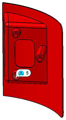
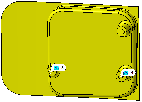
•When completed, select [Close] to close the Feature Points dialog.