Moves have many parameters in common. Outlined below are the common parameters that are to be defined for all moves. Following the outline of the common parameters, each move will be outlined with its specific parameters.
|
Commands
Name: This defines the name of the move that is to be created. Generating a report will utilize the names of the moves; 3DCS may also show a move as a Contributor, if Floats are active and available.
Move Active: The move can be turned on or off by toggling the Active button. The parts associated with the move will not move if the move is turned off.
Animation: Check the Animation box to enable the animation of the move.
Help: The Help button is context sensitive; it will open the Help Manual at the required move page.
Description: A description for the move can be typed in to the box. This description is an option and helps users to describe the move in their own words.
Options: Contains the Hole/Pin float and Bend move parameters. See Move Options for detailed information.
Object Features or Points: These are the features or points on the object used to locate the part(s) to the target. The All Objects feature lets the user select all of the object points at one time.
Target Features or Points: These are the features or points on the target corresponding to the object features or points. The All Targets feature lets the user select all of the target features or points at one time.
Move Parts: Lists all the parts that are associated with the object features or points, as well as other parts associated with the move.
Clicking on Add brings up the click tree window dialog box. Click on the parts that are associated with the object features or points of the move. The part can be selected by Keying In Part Name.
To delete a part from the list, select the part that is to be deleted and select the Delete button.
Parts and Assemblies are automatically added based on the object features or points selected in the move.
Show Direction: Displays the direction of the points selected in the Move. Press the Close button to return to the move.
Show Features: Displays the points or features that are selected in the Move. Press the Close button to return to the move.
Add New: This button resets the dialog to its default state, allowing users to start creating a new move (of the same type) without closing and reopening the window. (No Features, default Directions, no Conditional/Iterative Logic).
Add Note: Add text or images that will be included in the Report.
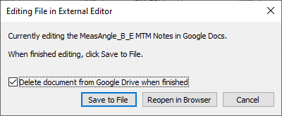
•If using Google Docs, edit the notes, return to 3DCS and select [Save to File] button.
oDelete document from Google Drive when finished - removes the Doc from the user's Google Drive.
Notes:
•When creating a new Note or Editing a Note within any MTM or GD&T dialog, Word will open. Once the user closes Word or the External Editor dialog, the HTML will be saved in the correct format and saved with the model. Users can Close Microsoft Word with the Notes and Images, but will need to select Yes and Yes: first to save the Note and Image to the dcstemp.htm and Yes to save the correct HTML format.
Save View: Saves a the current orientation and position of the assembly. This view will also be used in a Model Report.
Show View: Displays the view defined by Save View function.
Summary: The summary button displays the measurement's information in a notepad. The Measurement Summary will also detail more information that is not shown in the dialog (Point Names, Point or Feature Size, Point or Feature XYZ location.)
Directions
Direction Index: Lists all the input directions necessary for performing the measurement.
Direction Type: There are six different direction types for moves: Type In, Two Points, Normal, Associated Direction (AssocDir), Pick Point Direction (PickPtDir) and Auto. See: Vector Direction for more information about each direction.
Direction Number: Shows the number of input directions required to perform the measure. Some measures have the option to add more than one direction. This should associate with the amount of features or points used in the measure.
Direction Mode: Sets the Move to either Object Plane or Target Plane depending on how the points are matching. Most applications have the plane associated with the target. However Object Plane is useful when the object has a slot locating to the targets pin.