The [Options] button brings up the Move Options dialog box which contains settings for Hole and Pin Floating, Measurement Logic (Conditional and Iterative), and Bend conditions.
Move Floats Float Offset Conditional Logic Iterative Logic
|
Move Float Options:
If there are no Hole and Pin features, this area will be blank.
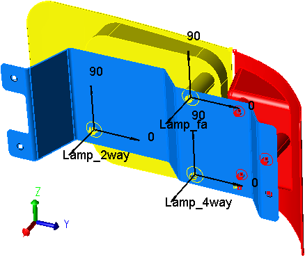
Floating describes how a pin moves within a hole or slot. It is necessary to model floating in an assembly because often a large part of the assembly variation originates from the play or floating of assembly or fixture pins within their mating holes. The maximum amount of float between a pin and hole is the difference between their diameters. Since most holes and pins have a size tolerance, their diameters vary and the amount of float varies accordingly.
3DCS first determines which matching pairs of objects and target points have holes and pins (or slots) associated to them. The pulldown menu lists all the Hole-Pin and Slot-Pin matchups for the move. In the Move Options dialog box shown above, there is a match-up between object point (O4) and target point (T4). If this matchup of points were to be used more than once for defining the move, the Hole-Pin matchup would only show up once in the Move Options dialog box.
When a check is present in the Active checkbox, the pin is allowed to float within the hole according to the method specified.
Rand Index: Rand#1
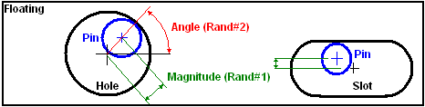
Magnitude
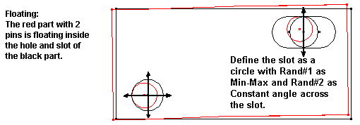
Magnitude describes how far from its nominal centerline it will float. The distribution specified is spread across the diameter of the possible float range. If the Magnitude distribution is specified as Constant, the pin will always float to the edge of the hole. However for a slot, a constant magnitude will always float the pin to only one edge of the slot. For the pin to float to both sides of the slot, a BiMode distribution must be specified.
The different types of distributions are outlined in Distributions.
Sigma Number
The multiplier for the Standard Deviation value(s). This value is multiplied with the Standard Deviation(s) to define the range of the distribution. The Sigma value is an integer between 1 and 8. By default the multiplier is set at 3. This specification is required for Normal, Weibull, Step, Left Skew, Right Skew, Open Up and Open down distributions.
Range Scale
The Scale field is used to specify a multiplication factor. For instance if the user specifies 2, the tolerance is multiplied by a factor of 2. The default is set at 1.
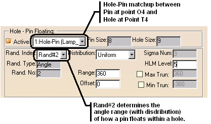
Rand Index: Rand #2
Angle (Degrees)
The Angle parameter specifies the angle range for the Pin to float inside its matching Hole. For a pin to float randomly (at any angle) inside a hole, a range of 360 degrees with a Uniform distribution should be specified.
Sometimes it is necessary to model a manufacturing process where the pin is more likely to float to the top side of the hole due to the effects of gravity. Then a smaller angle range (perhaps 60 degree range with an offset of 90 degrees) would float the pin in the more accurately.
The user should verify that the part is floating properly by using zoom-in to examine the Hole-Pin matchup and then using the Sweep or Deviate functions to animate the parts. See Deviate/Sweep. Slot-Pin matchups do not have an Rand#2 because they do not float at any angle, only a magnitude.
Range: The angular range of variation. The default is 360°.
Offset: The deviation from the nominal. The default is 0o.
Min Truncation: Truncation means to cut off at a certain point. Min Truncation means to cut the distribution at a particular low end point. The default is 0o which means no truncation.
Max Truncation: The value by which the maximum angular tolerance needs to be truncated. The default is 360o (no truncation).
Rand #2 (angle random type), users can use Pick Constant Angle, which allows picking points or features to define the direction of the floating. The user will set the direction in the Pick Vector dialog and the Offset angle will be automatically calculated. The Distribution will be set to Constant but may be modified. This is not a dynamic function.
Hole/Pin Floating Methods:
Phantom Point Method
•The Hole Phantom Point
oThe Hole Phantom Point is the copy of the center point of the hole/pin in target. This copy is deviated in the circle plane by the hole/pin clearance.
oThe hole/pin clearance is calculated as follows:
For Magnitude:
![]()
For Angle:
![]()
oAfter positioning the Phantom Point the object point is moved to it.
•The Slot Phantom Point
oThe Slot Phantom Point is deviated in arc created from the previous point in the move list.
oAfter floating the 4-way and positioning the object hole/pin center point start rotating the target Phantom point (the copy of the center of the target pin). The rotation angle is given by the next formula:
![]()
oThe Slot size is the distance between points 1 and 2 obtained by rotating the line between the two centers (deviated object center point, for 4-way and target's pin center point, for 2-way) until the line meets slot's edges (see below):
If the object has one hole and two slots to float the order to deviate is: HOLE SLOT1 |
•Interference Checking (Jiggle move)
oCheck the interference between hole-pin sets and re-float "X" number times till it fits. See below.
•Pattern Float
oFloats a part with pattern pins or holes to a mating part with corresponding points.
Conditional Logic: This option is chosen if a Move is to be activated, based on the condition of a particular Active Measurement in the model. Any one of the previously defined Measurements can be selected from the Conditional Logic drop-down menu as a condition to be satisfied before completing the Move. When that particular measurement value is within the specified Measurement limits, the Move is activated.
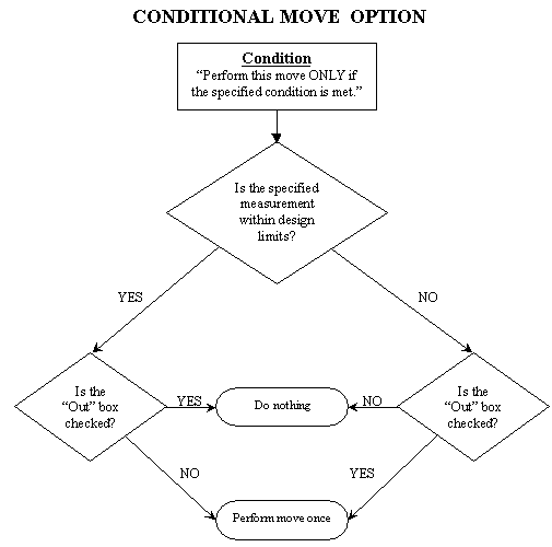
Checking the Out box will activate the move when the measurement value is outside the specified limits. The default is None in the measurement selection box. This is a one time conditional check done in each assembly build sequence.
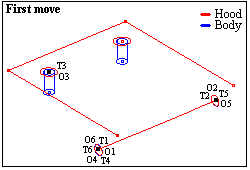
A check is made (Meas1) between the right stop and the contact point on the hood. The specification is set at 0.00 to 100.00.
If, after the first move, this check is positive, it means that the hood came in contact with the left stop first. If Meas1 is negative, there is an interference between the right stop and hood, meaning that the hood should have been moved to the right stop.
The second move locates the hood to the same hood hinges and to the right stop, ONLY if Meas1 is negative (not within it's specification).
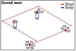
Under Move Options, Condition, the measurement Meas1 is selected. The out box is also checked.
This means that if this output is out of spec (negative means that the left stop is interfering with the hood), then complete this move (the second move). If the output is within the spec (positive means no interference) this move is not performed.
The check is performed before the move is executed. The Out box is only associated with the conditional statement. It has no association with the Interference statement. |
Example Model: C:\Users\Public\Documents\DCS\V5_8_2_0_0\3DCS CAD & Example Models\Reference Models\Moves\Conditional Logic
This option is chosen in the following situations:
•When a condition necessary to satisfy an iteration move needs to be defined.
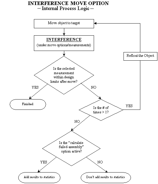
•To check the interference between a hole-pin or slot-pin match up and report the failure rate based on the total assembly builds.
A measurement that defines the Iterative Logic option between a hole-pin or a slot-pin match up, is specified in the Interference drop-down list. This previously defined Active measurement that sets up the iteration limits, is selected from the measurement list under the Interference section. The number of times the move should perform the interference check, in order to satisfy the condition, is input in the Iterations box.
The Interference Logic measurement is a condition check that is performed after the Move is executed.
•The iteration move will try to satisfy the limits of the measurement within the number of times specified. The move may find no solution if the condition is not matched within the number of times specified.
•The interference condition will calculate the number of times there was an interference with the hole-pin or slot-pin match up and report the failure rate, based on the total assembly builds.
•The default is set to None in the measurement selection box.
See example "Interference.w3d". The model shows how to float moves on pins and circles.
NOTE: This is a condition check that is performed after the move is executed.
Bend Moves:
This area contains Bend Locations and Bend Plane Direction.
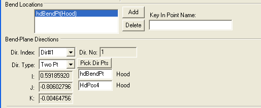
Bend Locations contains a drop-down box listing the points used in the bend move.
Note: If more than one point is used in the same bend move, only the area that results from intersecting all bend areas, will bend.
Bend-Plane Directions contains:
•Dir. Index - lists all direction for bends.
•Dir. No - shows the number of directions.
•Dir. Type - shows the direction type. See Vector Direction.
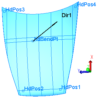
•Show Bends - activates the Graph window showing the point(s) and direction(s) for the bends.
See also: Bend Routines.
Show - Bends: show the bending point(s) and direction. The part will bend starting from the Bending Pt, in the bending direction. The rest of the part will not deform.
Floats will show the floating direction for the hole/pin pairs included in the move.