The display tab holds options to change labels in 3DCS and the Graphics window.
|
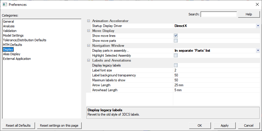
Start-up Display Driver: This setting selects the Graphics Driver to be used when the Animation Accelerator is used. Users can pick either OpenGL or DirectX.
Move Display:
Show Move Lines: Shows a line between the object and target in the move. (Only works for Compliant Moves).
Show Move Part: Highlights the part which will move in the highlighted move.
Solid Deviation: Replace 3DCS Mesh with solid surface.Fills in the mesh wire-frame with a "skin." Useful for visualization.
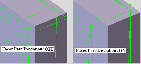
Facet Part Deviation: Sews 3DCS mesh at the common nodes between adjacent faces, to make the part appear and deviate as a solid. When the Facet Part Deviation is turned off unconnected meshed faces will deviate independent from each other. To connect the mesh faces and deviate them together, turn the feature on.
Hide CAD point after converting: Automatically hide CATIA points after they have been converted to DCS points or Feature points. This is helpful when trying to select the points after they have been converted.
Mesh Large Faces: Will allow 3DCS to attempt to mesh any surface in the model. When inactive, large surfaces are not meshed to prevent 3DCS from slowing.
CGR Mode: CGR Mode is for Ray Trace options ONLY. This will not change the actual model CGR or how it is created.
Create CGR: 3DCS default setting. This mode creates a CGR from the geometry/catpart. When Animation mode is activated, the actual geometry/catpart is hidden and the DCS CGRs in the DCS rep are displayed, move, and deform. The DCS CGRs are morphed instead of the actual geometry/catpart. We must get the upstream materials and colors ourselves with this method (e.g. Ray Trace does not work well with DCS rep in regards to materials).
Use CAT Rep: Replaces the 3DCS created CGR with CATIA V5 created CGR files. This mode works directly on catia's rep for the geometry/catpart. 3DCS will move and deform the actual geometry/catpart. Upstream materials and colors are in these reps so we do not need to be concerned with dealing with them (e.g. Ray Trace works). Animation and Creation mode will act the same in this setting.
Duplicate Rep: Creates 3DCS CGRs in the CATIA V5 CGR folder. Like Create CGR, we create CGRs from the geometry/catpart. However, instead of putting them in our DCS rep we put them in Catia's rep at the same level as its corresponding geometry/catpart rep and hide the catia geometry/catpart rep. Upstream materials and colors are in these reps so we do not need to be concerned with dealing with them (e.g. Ray Trace works).
CGR management: Displays the Part Annotation in Animation Mode. Update CGR need to be done to apply this setting. Applies only in Create CGR Mode.
If any Multi-Instance parts while Using CAT Rep or Duplicate Rep may prevent 3DCS data (Points and mesh) from moving with a move. Break the link, make unique parts or change the CGR Mode to Create CGR. (75267) |
Display legacy labels: Toggle to switch between the Legacy Labels or Annotations in the graphics for 3DCS features, points, MTMs and GD&T.
Label zooming: Sets the size of labels pertaining to either Screen or the Parts. (Only for new Annotations setting).
•Constant size: The labels are not zoom-able and remain screen sized in the graphics window
•Zoom with model: Labels will remain one size; the user can zoom in and out of the labels.
Label font size: Edits the font size of the MTM, Contributor, Point, Feature and Analysis Window fonts. (Default is set to 3; Only for new Annotations setting).
Maximum labels to show: Adjust the amount of highlighted labels when selecting an MTM and GD&T in the tree, or from Show Features function in the MTM and GD&T dialogs. Allowing more labels to be shown may reduce performance. Default is set to 50 labels. (Only for new Annotations setting).
Background Color and Transparency: Sets the background color and transparency of the labels. (Only for new Annotations setting).
Arrow zooming: Sets the size of arrows pertaining to either Screen or the Parts. (For both Legacy Labels and Annotation settings)
•Constant size: The arrows are not zoom-able and remain screen sized in the graphics window
•zoom with model: Arrows will remain one size; the user can zoom in and out of the labels.
Arrow length: Set the total length of arrows drawn in annotations. (For both Legacy Labels and Annotation settings)
Arrowhead length: Set the length of arrowheads in arrows drawn in annotations. (For both Legacy Labels and Annotation settings)
Note: Both Arrow length and Arrowhead length will be displayed with units
Rep Selection
Point rep selection: Allows selection of the created Points when working in ![]() Animation Mode. Switch the display to
Animation Mode. Switch the display to ![]() Animation Mode. Edit or a create a MTM or GD&T dialog. Move the mouse pointer over a point. Notice the point and/or label is highlighted.
Animation Mode. Edit or a create a MTM or GD&T dialog. Move the mouse pointer over a point. Notice the point and/or label is highlighted.
Surface rep selection: Allows selection of created Surfaces when working in ![]() Animation Mode. Edit or a create a MTM or GD&T dialog. Move the mouse pointer over a 3DCS Surface (mesh). Notice the Surface is highlighted.
Animation Mode. Edit or a create a MTM or GD&T dialog. Move the mouse pointer over a 3DCS Surface (mesh). Notice the Surface is highlighted.
Navigation Window
Display parts in assembly: Method to display parts in the tree.
•In separate "Parts" list: Parts are contained in a list titled "Parts" which displays the number of parts under the selected level.
•Directly underneath parent part: Parts are listed underneath their parent part/assembly.
Highlight Selected Assembly: When selecting the assembly in the Model Navigator, this setting will highlight all the parts within the selected assembly. Deactivating this setting may improve performance.
Scroll Model Navigator to the selected CAD Part: This setting will scroll the model navigator to the part or feature when its is selected from graphics or from the Cad Tree.
Default Window Type: Sets whether the Tree Window or Navigation window is displayed by default
•Tree window (Legacy): Tree Window is displayed when opening a model.
•Model Navigator: The Model Navigator is displayed when opening a model.
Prompt for HSF File Loading: When loading HSF files, 3DCS will open the Load Management dialog. Useful for larger models.
Solid Deviation: Displays Analysis Mesh as Solid Surface
Facet Part Deviation (stitch analysis meshes): Sews the surfaces to deviate multiple surfaces as one surface.
Save GFX file (Visualization file): Save the graphics information in a file along with the WTX file.
Part colors: Sets how parts are colored in the graphics.
•3DCS colors: Part and line color comes from 3DCS.
•Surfaces uses HSF colors, lines uses 3DCS colors: Part color comes from the imported HSF. Line color comes from 3DCS.
•HSF colors (slower loading): Part and line color comes from the imported HSF.
Advanced graphics settings: Open the graphics window options dialog.