Alias Display is a nomenclature (naming) feature in 3DCS. It takes all available 3DCS feature names (Moves, Tolerances and Measures), part names, coordinates, vector directions, tolerance range, and more, and applies them to the feature name as an alias. This feature can be best used when creating a 3DCS Report and reviewing a model to understand how the model was built. All these settings is saved along with the Model.
Parameter Name to Use: User can enter the given CAD Attribute or Parameter Name and the value of those will be used for the Part Names. This setting will be saved with the model
Alias Display utilization:•Efficiently create a standardized naming convention •Easily obtain naming standard across models •Details the naming standard in 3DCS Reports and Simulations •Improves model quality and validation |
|
Within this section:•Part Name Customization •Abbreviation File |
See Also...Community: Alias Display |
Initials |
Alias |
Description |
Initials |
Alias |
Description |
|---|---|---|---|---|---|
#IN# |
CAD Part Name |
Add and use the CAD Part name. Editing the Part or assembly, and Updating will update the CAD Part Name |
#DN# |
Add a name the user can edit and change for the part or assembly. |
|
#RD# |
Reference Description |
|
#RN# |
Reference Name |
The Name entered in the Reference Name field will be used. |
Initials |
Alias |
Description |
Initials |
Alias |
Description |
|---|---|---|---|---|---|
#IN# |
Instance Name (CAD Part Name) |
Shows the CAD Part name. Editing the Part or assembly, and Updating will update the CAD Part Name |
#DN# |
Add a name the user can edit and change for the part or assembly. |
|
#RD# |
Reference Description |
Shows the Description information, under the Reference tab |
#RN# |
Reference Name |
Shows the Name from the Reference tab. |
#ID# |
Instance Description |
Shows the Description from under the Instance tab. |
|
|
|
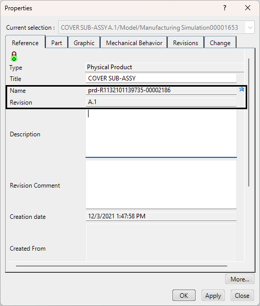
Assembly and sub-assembly level: (Reference Description, Reference Name)1.Right-click on the Assembly/sub-assembly in the 3DEXPERIENCE tree. 2.Edit or check the Name or Revision in the dialog.
|
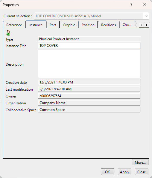
Assembly, sub-assembly and parts: (Instance Description, Instance Name, Reference Description, Reference Name)1.Right-click on the part in the 3DEXPERIENCE tree. 2.Edit or check the Instance Title or Description in the dialog.
|
Initials |
Alias |
Description |
Initials |
Alias |
Description |
|---|---|---|---|---|---|
#IN# |
CAD Part Name |
Add and use the CAD Part name. Editing the Part or assembly, and Updating will update the CAD Part Name |
#DN# |
Add a name the user can edit and change for the part or assembly. |
|
Use Attributes from NX:1. Right Click the Name from tree to open the Properties Dialog. 2. Go to the Attributes Tab to create a new Attribute Name in the Field Title/Alias and Enter the Part Name in the “Value” field which you wish to see in the 3DCS Model Navigator 3. Right click the top header bar where it says 'Descriptive Part Name' and select Column 4. Add this Attribute to the column to see it in the NX Model Navigator. 5. In 3DCS Preferences 6. Now Update Model to see the Attribute Name in the 3DCS Model Navigator |
|||||
Initials |
Alias |
Description |
Initials |
Alias |
Description |
|---|---|---|---|---|---|
#IN# |
CAD Part Name |
Add and use the CAD Part name. Editing the Part or assembly, and Updating will update the CAD Part Name |
#DN# |
Add a name the user can edit and change for the part or assembly. |
|
Parameter name to use: User can enter the given CAD Attribute or Parameter Name and the value, which can be used for the Part Names. 1.Open the part in a new window, or edit the part. 2.Switch to the Tools tab and select [ ] Parameters. 3.Add a Parameter, add a Name and switch the type to STRING, add a name to the string field. 4.In 3DCS, open the Preferences and select the Alias Display section. 5.Type the name of the Parameter into the field: Parameter name to use. 6.Select OK in Preferences and Update Model.
|
|||||
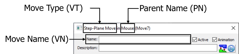
Notes:•Move Name (VN) will always be displayed, even when removing the abbreviation from field. •If more than one item is applied, such as directions, Object/Target features, or option (Iteration Loop and Rotation/Translate), only one can be shown at a time.
|
|---|
|
|---|
|
||||||||||||||||||||||||||||||||||||||||||||||||||||||||||||||||||||||
|---|---|---|---|---|---|---|---|---|---|---|---|---|---|---|---|---|---|---|---|---|---|---|---|---|---|---|---|---|---|---|---|---|---|---|---|---|---|---|---|---|---|---|---|---|---|---|---|---|---|---|---|---|---|---|---|---|---|---|---|---|---|---|---|---|---|---|---|---|---|---|
|
|||||||||||||||||||||||||||||||||||||||||||||||||||||||||||||||||||||||||||||||||||||||||||||||||||||||||||||||||||||||||||||||||||||||||||||||||||||||||||||||
|---|---|---|---|---|---|---|---|---|---|---|---|---|---|---|---|---|---|---|---|---|---|---|---|---|---|---|---|---|---|---|---|---|---|---|---|---|---|---|---|---|---|---|---|---|---|---|---|---|---|---|---|---|---|---|---|---|---|---|---|---|---|---|---|---|---|---|---|---|---|---|---|---|---|---|---|---|---|---|---|---|---|---|---|---|---|---|---|---|---|---|---|---|---|---|---|---|---|---|---|---|---|---|---|---|---|---|---|---|---|---|---|---|---|---|---|---|---|---|---|---|---|---|---|---|---|---|---|---|---|---|---|---|---|---|---|---|---|---|---|---|---|---|---|---|---|---|---|---|---|---|---|---|---|---|---|---|---|---|---|
Options
Part Name Abbreviation: Alias Display takes advantage of available part names within the assembly. The user can specify either the Prefex or Suffix of the part name.
Part Name number of characters: Length in characters of the prefix/suffix to be shown.
Decimal Precision: Is referring to any numerical value for each node; such as Range for Tolerances and GD&T, or Vector direction in Points, Moves, etc. For example, if the Precision value is set to 3, the value in the display will show 3 trailing zeros. (Range of 1 = 1.000).
Abbreviations: Copy the features from the Abbreviation File and paste the contents of the file when you select [Edit Abbreviation File] from the ![]() Preferences
Preferences ![]() Alias Display tab. The file can also be located here: C:\Users\Public\Documents\DCS\3DCS_V5_8_2_0_0\Help Manual.
Alias Display tab. The file can also be located here: C:\Users\Public\Documents\DCS\3DCS_V5_8_2_0_0\Help Manual.
Edit Abbreviation File: The abbreviation file is an editable file that holds all abbreviations in 3DCS. So if a user wants to use Alias Display but wants to display the Six-Plane move as "6P" or other, the abbreviation file can be edited to display what the user wants. Any information set in the file will be shown in 3DCS, as long as Alias Display is active for moves. It will also be shown in the user's HTML Report.
Reload the Abbreviation File:If any changes are made on the fly to the Abbreviation File, the user will need to reload the information into 3DCS. Use [Reload the Abbreviation File] to load any new abbreviation.
Notes: •By default, any source used in Alias Display (MTM, GD&T, Point or Feature) will have their name displayed. Such as using FN (Feature Name), which can be removed from the feature display field, but will always display the name of the feature. •Alias Display settings are saved in the 3DCS config file, which means when ever a user starts a model, Alias Display will be active for each of their models. •Duplicate abbreviations are allowed in 3DCS and in the text file. •Instance Title will be used in the Excel Export by default. To use the Reference Name in Excel need to set the "UseInstanceName " value to "0" in the config file. •Special keys are available to use to separate each node feature: "(!@#$%^&*|_)", "---". •Points and Features will display the Vector Direction (FV) (i,j,k,) when Dominant Direction is selected. |