|
|
|
How to project a select set of Coordinate points to non-existing features:
1.Select the ![]() Auto Point Projection dialog, from under the
Auto Point Projection dialog, from under the ![]() Feature point icon.
Feature point icon.
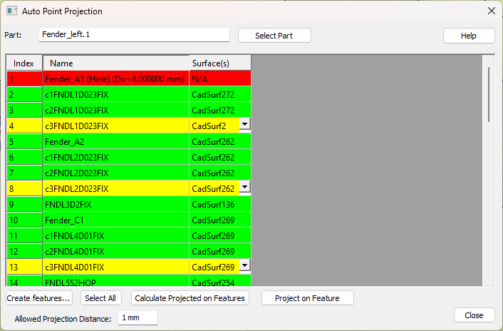
2.Select a part containing the coordinate points to be projected. The Auto Point Projection dialog will open displaying all the coordinate points within the part.
Note:The best practice for this step is to manually create features, as this saves time. Auto-generating surfaces may take slightly longer, depending on the size of the part.
3.Now the dialog will list all the features that was calculated for the points.
4.Select the [Project on Feature]. This will project all the selected points to its calculated surfaces This will not be available until the user selects [Calculate the Projected Feature].
5.The dialog will re-open, either empty, if all the points were successfully projected, or containing points that couldn't be projected.
Commands
Create Features: The user can use this option and start creating the features by clicking on the CAD surfaces on to which the points need to be projected.
Select All: This will select all the points in the dialog.
Allowed Projection Distance: This is distance zone from the point that the software uses to calculate the projected surface.
Calculate Projected Feature: This option will prompt to "Auto generate surfaces" the user can say "No" if they have already manually created the surface. If the user select "Yes" then the software will check all the features within the given projected zone and automatically creates features for projection.
Row Color definitions:
•Point line in the dialog is Green if the Surface calculated was successful.
•Point line in the dialog is Red if the Surface was not found
•Point line in the dialog is Yellow if there was more than one possible Surface was calculated, which the user can use the drop-down to manually pick the needed surface.
Will the Auto Point Projection project Coordinate Points with diameters?
No. The dialog will show Points with Diameter as Red in the dialog.
What's the differences between this function and the Project Point within the Feature Point dialog?
The Auto Point Projection function will work faster on a larger scale.
The Project Point function, within the Feature Point dialog, will only handle 1 or more points on 1 feature.