Modeling points form the basic framework and structure for a 3DCS simulation model.
The 3DCS Model Creation Toolbar contains features that can be created for analysis modeling:
|
Points Use |
|||
|---|---|---|---|
Point Type |
Name |
Link Type |
Description |
|
Not referenced to any surface |
Coordinate Points are points created in space, or defined by an XYZ location. The Coordinate Point can be defined as a Feature of Size, such as a Hole or a Pin. It can be used in a Rigid Body move, Tolerance or Measure. |
|
|
Coordinate Point: Defined as a Hole |
||
|
Coordinate Point: Defined as a Pin |
||
|
Linked to a Surface or a CAD Point |
Feature Points can be created on features and defined as either a Point on a Surface, or a Center Point of a Feature of Size. When a Feature Point is created on a surface, it will inherit the material direction of the surface or the axis direction of a Hole or Pin feature. |
|
|
Feature Point: Defined as a Hole |
||
|
Feature Point: Defined as a Pin |
||
|
Feature Point: Defined as a Hole - Circle Edge point |
||
|
Feature Point: Defined as a Pin - Circle Edge point |
||
|
Feature Point: Defined as a point on an Edge |
||
|
Hole: Defined as a Cone feature |
||
|
Pin: Defined as a Cone feature |
||
|
Hole: Defined as a Sphere feature |
||
|
Pin: Defined as a Sphere feature |
||
|
Linked to two DCS or Feature Points |
Dynamic Points can be created by using one or two Coordinate or Feature Points, to either create an offset point or a center point between two points. |
|
Features Use |
||
Feature Type |
Name |
Description |
|
Feature: Defined as a Plane |
Most features used in 3DCS are defined as a Plane. If 3DCS cannot detect a diameter from the selected surface, it can be shown as a Feature but without any geometry type (Plane, Cylinder, etc.). |
|
Hole: Defined as a Cylinder feature |
Features created using a Feature Point will be defined in the Features list. |
|
Pin: Defined as a Cylinder feature |
|
|
Edge: Defined as a Hole |
|
|
Edge: Defined as a Pin |
|
|
Edge: Defined as a Line |
|
|
Hole: Defined as a Cone feature |
|
|
Pin: Defined as a Cone feature |
|
|
Hole: Defined as a Sphere feature |
|
|
Pin: Defined as a Sphere feature |
|
|
A Group of Points can be created to define a Plane or an Edge in 3DCS. |
|
|
A group of Features to use in the Dimensioning Location tolerance. |
|
|
Slot or Tab features are used to define a Feature of Size. This feature can be used in a Move to define a Two-Way locator. |
|
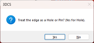
Edges - Hole and Pin creation: When selecting an edge when creating a Feature Point or through a MTM/GD&T dialog, 3DCS will ask whether the user will define the edge as a Hole or Pin.
1.In any dialog (for example: GD&T Size Tolerance or Circular Tolerance), select an Edge.
2.If the edge is a complete Feature of Size (i.e., Pin or Hole type; Complete being an entire circle, not segmented). Users will be asked whether to create the edge as a Hole (Yes) or Pin (No).
To switch the Edge from a hole to a pin, or pin to hole:
1.Open the Feature Point dialog.
2.Select [Feature] and then select the Edge.
3.Select [Material] to switch the hole to a pin, or pin to a hole.