The
CAD GD&T standard will also be set when extracting GD&T. If the Part and Root have different GD&T standards the root standard is what sets the model standard. If the part is selected to extract the GD&T then the part GD&T standard gets extracted. •If the ISO standard is used, the size GD&T extracted will have the Envelope On flag turned On. |
|
See also... |
Best Practices |
Procedure:
Extracting GD&T (FT&A/PMI) into 3DCS:
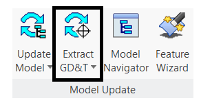
•Switch to the 3DCS work bench and hit ![]() Update Model, to load the model into 3DCS and to see the 3DCS Navigation Tree.
Update Model, to load the model into 3DCS and to see the 3DCS Navigation Tree.
•Select ![]() Extract GD&T.
Extract GD&T.
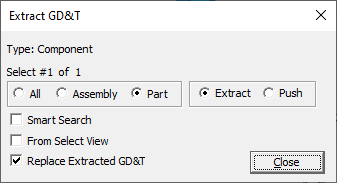
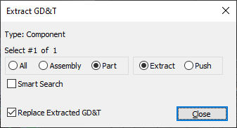
•This will open an ![]() Extract GD&T selection dialog prompting the user to select the component to extract the GD&T from. The user can either select an individual component or the root to extract the GD&T from all parts in the model.
Extract GD&T selection dialog prompting the user to select the component to extract the GD&T from. The user can either select an individual component or the root to extract the GD&T from all parts in the model.
•Selection can be done either from the NX Navigation Tree or 3DCS Navigation Tree and the NX Graphics Window.
The extracted GD&T will be displayed in the 3DCS Navigation Tree within each part.
The extracted GD&T will have unique tree icon ![]() to differentiate from the 3DCS created GD&T.
to differentiate from the 3DCS created GD&T.
•The name entered in NX is extracted with the GD&T and is the displayed name in 3DCS.
•In 3DCS, the GD&T dialog for each part lists all extracted GD&T.
Commands:
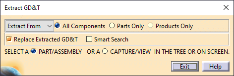
Extract From: Specifies the GD&T embedded in the CAD data will be added to or update the 3DCS model. When part of the 3DCS model, the call-outs are referred to as 3DCS GD&T.
Push To: Embedded GD&T will be updated with Name, range and offset changes from the 3DCS GD&T.
Searching Filters:
•All Components: 3DCS will search everything of the selected component and it's children
•Parts Only: 3DCS will only search in parts for GD&T.
•Products Only: 3DCS will search for assembly GD&T.
Smart Search: If any Moves or Measures already exist in the model, 3DCS only extracts GD&T from the features used from the current Moves and Measures.
When using the Extract From setting, the Replace Extracted GD&T and Smart Search options can be used.
If Active:
•Deletes existing GD&T.
•Creates new GD&T based on MTM Default settings.
•Feature Points may be automatically created:
oFor Datum Targets.
oBased on the Auto Feature Point Creation method set in preferences.
If Inactive:
•Updates features in existing GD&T.
•Creates new GD&T if not already added to the model.
•Retains name changes.
•With the replace option inactive:
oGD&T in the Model Variants dialog remains unchanged.
Selection:
•Part/Assembly: Allows the users select either a part or the assembly in the tree
•Capture/View: The user can either select a part or assembly/sub-assembly and add the GD&T, or by setting [Capture/View], the user can select a specific view in CATIA that the GD&T is created in.
•Select View: The User can select a specific View set and extract the GD&T only from that. To select a Part's View set, first the part need to made as work part and then the user can do the selection.
•From Current View: Activating this option will only extract the GD&T from the Current view of each Part/Assembly.
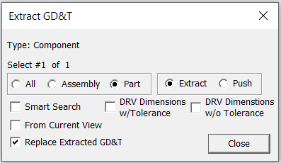
•DRV Dimensions w/ Tolerance: Will only extract the Driving Dimensions from the CAD which have tolerance attached.
•DRV Dimensions w/o Tolerance: Will only extract the Driving Dimensions from the CAD which do not have tolerance attached. This option helps the user to extract the dimensions from the CAD and the tolerance can be defined within the 3DCS GD&T dialog.
•Active: Extracts the GD&T only defined when the same Features are used with Feature Points, MTM's or GD&T.
•Inactive: Extracts all GD&T.
Note: •Duplicate FT&A names will be extracted and adding a "_n" to the names. •For a Model with mixed units, assembly units is what 3DCS uses on all parts on extracting GD&T. Datum Target Extraction Points are created for Datum Targets from the cursor location or from the points selected from the CAD. CAD Datum Targets created on Edges or lines will create Point on the Edge and the line on extraction and use the vector direction from the master referenced feature. The CadSurface where the points are created will be listed under the Datum as reference.
Dimensioning LocationLinear dimensions between 2 features that involves datum features will be extracted as Dimensioning Location and the origin will be assigned to the Datum Feature by default.
|