The ![]() Section Cutting tool allows users to cut the geometry and view different sections and interfaces. With the Sectioning license, users will be able to save multiple sections in the assembly, edit stored sections, export images as a bitmap or to drawings, and naming the section.
Section Cutting tool allows users to cut the geometry and view different sections and interfaces. With the Sectioning license, users will be able to save multiple sections in the assembly, edit stored sections, export images as a bitmap or to drawings, and naming the section.

Accessing the Section Cutting tool:
1.Open an assembly (*.CATProduct).
2.Make sure the workbench is opened to Assembly Design.
3.Find the Space Analysis toolbar and look for ![]() Section Cutting function, or type in the bottom left field 'c: Sectioning'.
Section Cutting function, or type in the bottom left field 'c: Sectioning'.
![]()


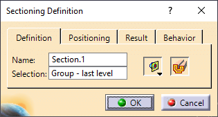
Using the Sectioning dialog - Definition tab:
•Give a name to the new Section. (Available with sectioning license only).
•The ![]() Volume Cut option will cut the geometry and show the internal parts within the section.
Volume Cut option will cut the geometry and show the internal parts within the section.
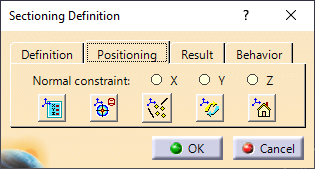
Positioning Tab:
•Select X, Y, or Z to apply the section plane normal to the X,Y,Z axis.
•Select ![]() Position and Dimensions to view or edit the Section planes location and width/height parameters.
Position and Dimensions to view or edit the Section planes location and width/height parameters.
•Select ![]() Geometric Target and select a plane (parallel) or edge (Perpendicular).
Geometric Target and select a plane (parallel) or edge (Perpendicular).
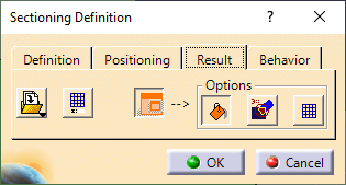
Results Tab:
•Select ![]() Section Viewer to view the section or edit the section with some viewing options.
Section Viewer to view the section or edit the section with some viewing options.
oRight-click in the Section Viewer to flip, rotate or lock the section.