When creating a 3D Tolerance Analysis Model, the MTM's can be created in any order. Moves first, then Tolerances, then Measurements or in any combination.When the software runs the Monte Carlo Simulation, it will apply the Tolerances first, then the Moves, then the Measurements. It will do this, starting with the lowest order or farthest most inboard child, working its way out to the highest most outboard parent in the tree.
|
To get the correct analysis results, the user needs to take into account the following:
Moves: Should always be at least one level above the parts or assemblies (being moved) it is applied to.
GD&T: The GD&T are generally applied to the part level. The sequence GD&T uses is different than 3DCS tolerances. GD&T starts by applying size tolerance, then Datums, then tolerances referenced by those Datums. To see the GD&T sequence and how it's simulated in the Monte Carlo Simulation, select the Auto Sort option available in the GD&T list dialog.
Tolerances: Are generally applied at the part level.
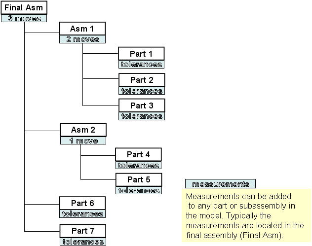
Measurements: Can be located anywhere in the assembly tree. Generally they are applied at the upper level parent assembly, or the top level assembly. The measurements will only pick up the variation at the level they are applied to. If a measurement is applied at the part level it will only read the detail part tolerances or variation. If it is applied at the top assembly level it will read the part tolerances plus the assembly variation caused by the moves.
Below is an Assembly tree illustrating the typical placement of MTM's.