Finally, we will look at the way tooling locates the Turnlamp to the Bracket in order to reduce variation at the assembly level. Previously, we defined the outboard pin as the 4-way locator for the Turnlamp so this is the pin that had the most control in the YZ plane. In this exercise, we will switch the clearance hole and the 4-way locator. This will allow the Upr_Gap measurement to be more closely controlled because the new 4-way locator pin is closer to the measure location. Plus, the new 4-way locator pin is farther away from the 2-way locator pin, reducing the effect of position variation.
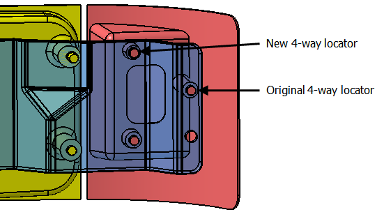
The TurnLp_Clear hole in the Bracket is a clearance hole so it has a larger diameter than TurnLp_YZ. We need to create a point on TurnLp_Clear with a smaller diameter so we can make a proper comparison of changing the locator.
•Open Lesson6Lamp_SubAsm_Lesson6Analyst_Tutorial_Lesson6
•With the Analyst_Tutorial_Lesson6 tab open, Go to the North quadrant of the Compass (called My Social and Collaborative Apps) and select the Collaborative Lifecycle app.
•Select the Analyst_Tutorial_Lesson6 Simulation and select ![]() Duplicate from the toolbar at the bottom.
Duplicate from the toolbar at the bottom.
•Right-click on the new duplicated Analyst_Tutorial_Lesson6 Simulation in the model tree and select Properties.
•In the Reference tab of the Properties dialog, change the Title to "Analyst_Tutorial_Lesson9c".
•In the Compass, go to the South Quadrant (called My Content and Simulation Apps) and select 3DCS Variation Analyst V6 in the V+R My Simulation Apps section to return to the 3DCS Variation Analyst workbench.
•Go to File ![]() Save Management.
Save Management.
•Select the Lesson6.CATProduct and select [Save As...].
•In the Save As dialog, rename the Product to "Lesson9c.CATProduct" and click [Save].
•In the Save Management dialog select [OK] to save the CATIA Product under its new name. The model is not actually saved until you click OK.
•Click the ![]() Application Button then select
Application Button then select ![]() Save As.
Save As.
•Change the File Name to "Lesson9c.wtx".
•Click [Save] in the Save As dialog.
•Go to File ![]() Save As.
Save As.
•In the Save a Copy dialog, enter "Lamp_SubAsm_Lesson9c" and make sure the Type is set to [Assembly (*.asm)]. Click [OK].
•In the Assembly Save a Copy dialog, click [Save Copy and Open].
•Close the 3DCS Model Navigator and Creo window for Lamp_SubAsm_Lesson6.
•Click ![]() Update Model in the new window for Lamp_SubAsm_Lesson9c.
Update Model in the new window for Lamp_SubAsm_Lesson9c.
•Go to File ![]() Save As.
Save As.
•In the Save As dialog, enter "Lamp_SubAsm_Lesson9c" as the new File name and make sure the type is set to [Part Files (*.prt)].
•Click [OK] to save the model and close the Save As dialog.
•Click ![]() Update Model.
Update Model.
•Go to File ![]() Save As.
Save As.
•In the Save As dialog, enter "Lamp_SubAsm_Lesson9c" for the File Name, make sure the Type is set to Assembly.
•Click [Save] to save the model and close the Save As dialog.
•Click ![]() Update Model.
Update Model.
•Click the ![]() Feature Points button.
Feature Points button.
•Select Center in the Feature Point ParametersPoint Method.
•Click [Feature][Select Feature] then select the feature T_TurnLp_Clear in the Bracket.
•Set the V component to 0.5.
•Click [Create Point(s)].
•Click [Close].
•Click the ![]() Points button then select the Bracket.
Points button then select the Bracket.
•Change the Name to "New_T_TurnLp_YZ".
•Click Convert to Coordinate Point(s).
•Set the Circle/Diameter to 8.5mm. This will simulate the smaller hole diameter.
•Click [OK] to close the Points dialog.
•Add a Size GD&T to New_T_TurnLp_YZ with a Range of 0.5mm. Name it Size_New_Locator_Hole.
•Add a Position GD&T to New_T_TurnLp_YZ with a Range of 1.0mm. Name it Position_New_Locator_Hole. The completed GD&T should look like the image below.
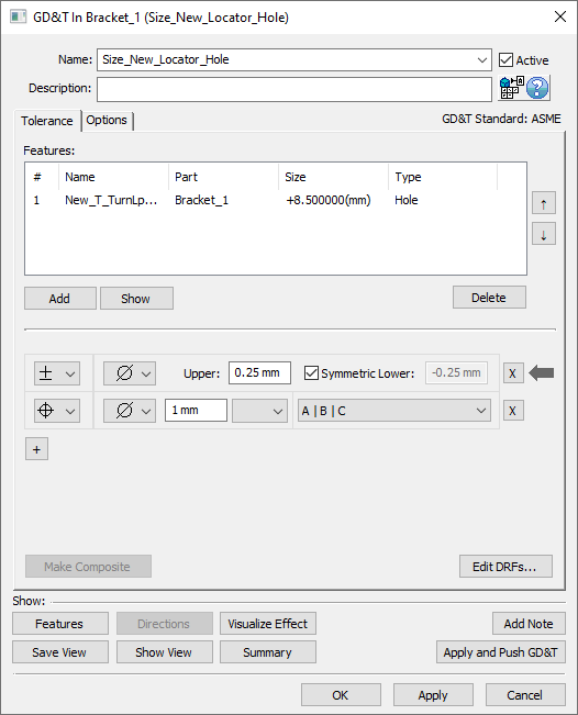
You should have something similar to the following image. Note that the point has a different diameter than the feature.
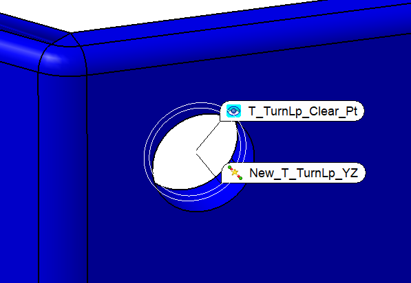
Now we need to update the move to use the new, smaller hole as the new 4-way locator.
•Open the Turnlamp-to-Bracket move.
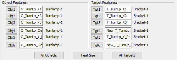
•Change Obj4 and Obj6 to the feature of the clearance pin in the Turnlamp.
Note: In this lesson we use the actual pin surface rather than create a point at the center of the pin as we've done in past lessons. This means that rather than us specifying what cross section of the pin to use (which is the best practice), 3DCS will just use the cross section at the middle of the axial length for the pin. When pins/holes are relatively short, as they are in this case, it is typically okay to just use the Feature instead of creating a point to specify the location of the cross section to use.
•Change Tgt4 and Tgt6 to the point New_T_TurnLp_YZ in the Bracket.
The updated move features should look like the image below.
•Click [OK] to save and close the move.
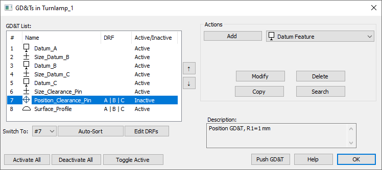
To treat the O_TurnLp_Clear pin as the datum feature of the Turnlamp, we need to turn off the position tolerance.
•Go into the GD&Ts of the Turnlamp, select Position_Clearance_Pin, and click [Toggle Active] to set it as Inactive.
•![]() Nominal Build and
Nominal Build and ![]() Run Analysis to compare the new results for Upr_Gap to the baseline model.
Run Analysis to compare the new results for Upr_Gap to the baseline model.
Before |
After |
|
Nominal |
6.00 mm |
6.00 mm |
6STD |
6.05 mm |
4.98 mm |
Your results may not match the above table
•Click ![]() Separate.
Separate.
•Save the model.
•Close the model.