Sometimes, the best way to reduce the amount of variation in an assembly is to change the geometry of the parts. The earlier this is done in the production cycle, the lower the cost of the change. In this lesson, we will look at the effect of shortening the outboard leg of the Turnlamp. 3DCS can simulate this change without modifying the CAD part. This change also requires a corresponding change to the Bracket. By performing an analysis before the design change is made to the CAD part, you can determine if the new design results in reduced variation.
•Open Lesson6Lamp_SubAsm_Lesson6Analyst_Tutorial_Lesson6
•With the Analyst_Tutorial_Lesson6 tab open, Go to the North quadrant of the Compass (called My Social and Collaborative Apps) and select the Collaborative Lifecycle app.
•Select the Analyst_Tutorial_Lesson6 Simulation and select ![]() Duplicate from the toolbar at the bottom.
Duplicate from the toolbar at the bottom.
•Right-click on the new duplicated Analyst_Tutorial_Lesson6 Simulation in the model tree and select Properties.
•In the Reference tab of the Properties dialog, change the Title to "Analyst_Tutorial_Lesson9b".
•In the Compass, go to the South Quadrant (called My Content and Simulation Apps) and select 3DCS Variation Analyst V6 in the V+R My Simulation Apps section to return to the 3DCS Variation Analyst workbench.
•Go to File ![]() Save Management.
Save Management.
•Select the Lesson6.CATProduct and select [Save As...].
•In the Save As dialog, rename the Product to "Lesson9b.CATProduct" and click [Save].
•In the Save Management dialog select [OK] to save the CATIA Product under its new name. The model is not actually saved until you click OK.
•Click the ![]() Application Button then select
Application Button then select ![]() Save As.
Save As.
•Change the File Name to "Lesson9b.wtx".
•Click [Save] in the Save As dialog.
•Go to File ![]() Save As.
Save As.
•In the Save a Copy dialog, enter "Lamp_SubAsm_Lesson9b" and make sure the Type is set to [Assembly (*.asm)]. Click [OK].
•In the Assembly Save a Copy dialog, click [Save Copy and Open].
•Close the 3DCS Model Navigator and Creo window for Lamp_SubAsm_Lesson6.
•Click ![]() Update Model in the new window for Lamp_SubAsm_Lesson9b.
Update Model in the new window for Lamp_SubAsm_Lesson9b.
•Go to File ![]() Save As.
Save As.
•In the Save As dialog, enter "Lamp_SubAsm_Lesson9b" as the new File name and make sure the type is set to [Part Files (*.prt)].
•Click [OK] to save the model and close the Save As dialog.
•Click ![]() Update Model.
Update Model.
•Go to File ![]() Save As.
Save As.
•In the Save as dialog, enter "Lamp_SubAsm_Lesson9b" for the File Name, make sure the Type is set to Assembly.
•Click [Save] to save the model and close the Save As dialog.
•Click ![]() Update Model.
Update Model.
•Select ![]() Nominal Build then
Nominal Build then ![]() Run Analysis with 2137 Total Runs again.
Run Analysis with 2137 Total Runs again.
•Set Show Contributors to Per Feature if not already set.
•Ensure Upr_Gap is highlighted in the Monte Carlo Analysis section of the Analysis Summary window.
In the Contributor Analysis section of the Analysis Summary window, notice the large GeoFactor value that is showing up for the top Feature of the Surface_Profile tolerance.

>>> Your results may not match the above illustration <<<
We will look at changing the geometry of the Turnlamp and Bracket to reduce this GeoFactor and reduce variation in the gap. The change we are proposing would look like the following.
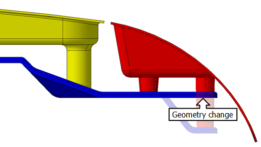
The length of the outboard pin is shortened and the mounting point is set closer to the gap, so the geometry will not have as much distance to amplify variation. 3DCS can simulate the change with points, so that the information needed to decide if this is the correct change can be generated prior to the work of changing the CAD parts.
First, we will create the points to simulate the design change.
•Close the Analysis Summary window.
•Click ![]() Separate.
Separate.
•Click ![]() Dynamic Point. This will open the Dynamic Points dialog.
Dynamic Point. This will open the Dynamic Points dialog.
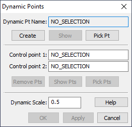
The Dynamic Point tool creates a Dynamic Point in the model. A Dynamic Point is a point that is not directly toleranced but gets its variation from the one or two Control Points that are used to create it. In this case, we are using one Control Point meaning that our new Dynamic Point will vary with the one Control Point but it will always be an exact distance above or below the Control Point along the direction of the Control Point's vector.
•Click [Create].
•Select the point O_TurnLp_X1 in the Turnlamp.
•Select the point O_TurnLp_X1 in the Turnlamp again.
•Set the Dynamic Scale as -30mm.
•Click [Apply]. This will create a Dynamic Offset point from O_TurnLp_X1. You should have something similar to the image below.

•Click [Create].
•Select the point O_TurnLp_YZ_Pt in the Turnlamp.
•Select the point O_TurnLp_YZ_Pt in the Turnlamp again.
•Set the Dynamic Scale as -30mm.
•Click [Apply]. This will create a Dynamic Offset point from O_TurnLp_YZ_Pt. You should have something similar to the image below. If your point was offset in the wrong direction, set the Dynamic Scale to 30mm then click [Apply].
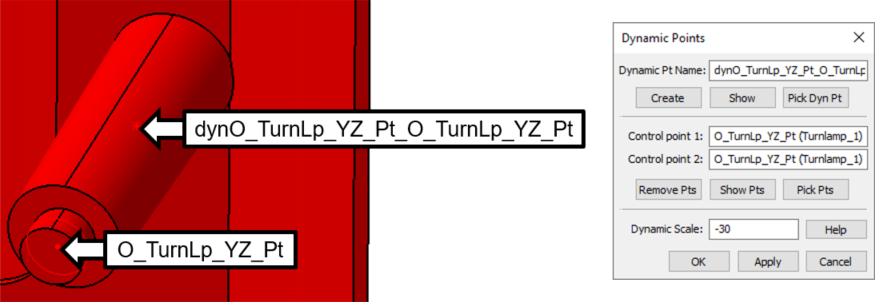
•Click [OK] to close the Dynamic Points dialog.
•Click the ![]() Points button then select the Turnlamp.
Points button then select the Turnlamp.
•Rename point "dynO_TurnLp_X1_O_TurnLp_X1 to "O_TurnLp_X1_Offset".
•Rename point "dynO_TurnLp_YZ_Pt_O_TurnLp_YZ_Pt" to "O_TurnLp_YZ_Pt_Offset".
As mentioned above, the Dynamic Points will follow the variation of the Control Points they were created from, so we do not need to add any location tolerance for the Dynamic Points. However, we do want the new point O_TurnLp_YZ_Pt_Offset to represent a pin in our geometry. It is important that we give this Coordinate Point a diameter because it will allow us to simulate hole-pin floating when we create the new Move. So, our next step is to make O_TurnLp_YZ_Pt_Offset a pin.
•In the Points dialog, select the point O_TurnLp_YZ_Pt_Offset then click [Convert to Coordinate Point(s)].
•Change the Circle/Diameter to 8mm.
•Click [Apply] in the Points dialog.
•Change the Circle Type to Pin.
The completed Points dialog should look like the following image.
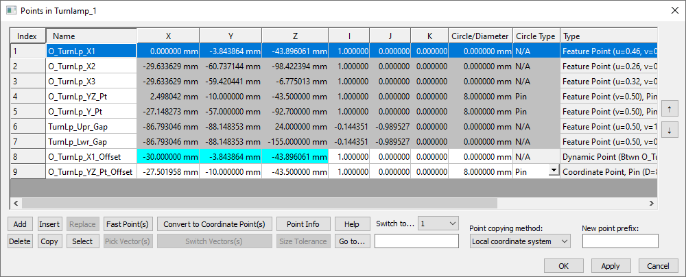
•Click [OK] in the Points dialog.
Next we will need to add variation to this new coordinate offset point. We want this point to be our new Datum B and have any GD&T associated to Datum B. To do this, we will remove the old features from Datum_B and Size_Datum_B and add the new coordinate point.
•Open Datum B in the Turnlamp part.
•Click O_TurnLp_YZ in the Features List and click [Delete].
•Click [Add] and select O_TurnLp_YZ_Pt_Offset. Click [Close] in the Select dialog.
The updated Datum B GD&T should look like the image below:
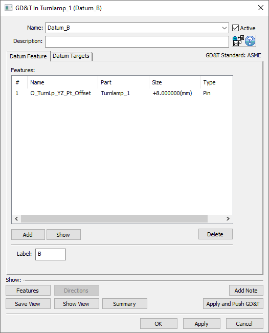
Repeat this process to add O_TurnLp_YZ_Pt_Offset to Size_Datum_B. The completed Size_Datum_B should look like the image below:

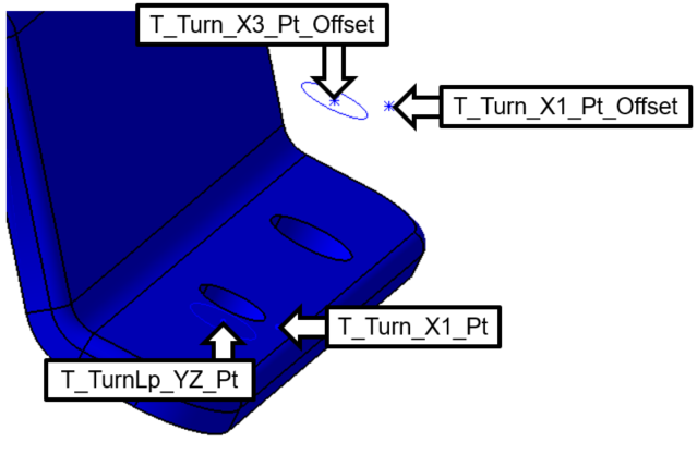
•Repeat this process to offset T_TurnLp_X1 and T_TurnLp_YZ_Pt in the Bracket 30mm. Make sure you offset the points in the correct direction.
•Rename the points as you did in the Turnlamp (but with "T"s for Target instead of "O"s for Object).
•Repeat the process done in the Turnlamp to change T_TurnLp_YZ_Pt_Offset in the Bracket to a Hole Type with a Diameter of 8.5mm.
You should end up with points similar to the following image.
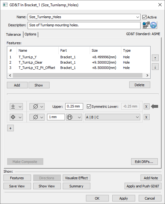
We will also need to add T_TurnLp_YZ_Pt_Offset to any GD&T that is applied to the original T_TurnLp_YZ_Pt. An easy way to check this is to right click on the original point either in the Navigation Tree or in the CAD and click Feature Info.... The MTM Info section of the Feature Point Info dialog will show that the point is used in 3 MTMs: Size_Turnlamp_Holes, Position_TurnLamp_Holes, and the Turnlamp-to-Bracket move. We will need to delete the old features in the GD&T found in this dialog and add our new point. This function is also a good way to see if a point or feature is used in the model before presuming it is unused and deleting it. The two completed GD&Ts should look like the image below:
These offset points need to be added to the move. We will create a copy of the Turnlamp-to-Bracket move to easily switch between both scenarios.
•Click the ![]() Moves button from the toolbar then select the Lamp_SubAsmLamp_SubAsm_Lesson9b.
Moves button from the toolbar then select the Lamp_SubAsmLamp_SubAsm_Lesson9b.
•Select the Turnlamp-to-Bracket move then click [Copy].
•Select the Turnlamp-to-Bracket move then click [Toggle Active] to set it as Inactive.
•Select the Copy_of_Turnlamp-to-Bracket move then click [Modify].
•Change the Name to "Turnlamp-to-Bracket_New_Geometry".
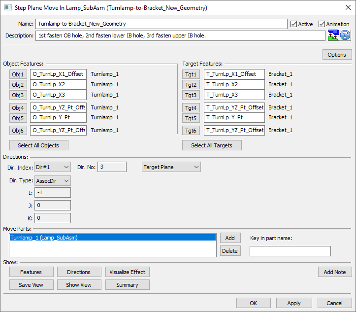
•Click [Obj1] then select O_TurnLp_X1_Offset in the Turnlamp.
•Click [Obj4] then select O_TurnLp_YZ_Pt_Offset in the Turnlamp.
•Click [Obj6] then select O_TurnLp_YZ_Pt_Offset in the Turnlamp.
•Click [Tgt1] then select T_TurnLp_X1_Offset in the Bracket.
•Click [Tgt4] then select T_TurnLp_YZ_Pt_Offset in the Bracket.
•Click [Tgt6] then select T_TurnLp_YZ_Pt_Offset in the Bracket.
The completed dialog should look like the following image.
•Click [Direction] at the bottom of the dialog.
Notice that the directions now come from the new Target points on we created as Dynamic Points above the Bracket.
•Click [Close].
•Click [OK] to save the move and close the dialog.
•Click [OK] to close the Moves dialog.
•Select ![]() Nominal Build then
Nominal Build then ![]() Run Analysis with Recommendation based on convergence on STD enabled.
Run Analysis with Recommendation based on convergence on STD enabled.
•Set Show Contributors to Per Feature if not already set.
For Upr_Gap, in the Contributor Analysis results of the Analysis Summary window notice that the Feature that was formerly our top contributor is now down to a much smaller contribution and, as expected, the GeoFactor value has also decreased substantially.
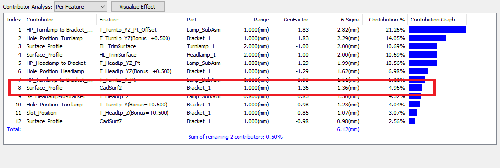
Note: If the Contribution % drops below 5% (as is the case with the image above) then the default filters will not display that contributor anymore. In the Contributors tab of the Analysis Options dialog the Min Show % can be reduced to also show contributors lower than 5%.
The GeoFactor on the Surface_Profile of the Bracket at the CadSurf to the Turnlamp has been reduced and the tolerance is no longer the largest contributor. Look up to the Monte Carlo Analysis section of the Analysis Summary dialog and notice the new statistics associated to the results of our new design.
Before |
After |
|
Nominal |
6.00 mm |
6.00 mm |
6STD |
6.05 mm |
5.60 mm |
Your results may not match the above table
If the new point was better for locating the Turnlamp, both the Turnlamp and Bracket geometry should be modified to match this change. If this is decided before tooling is built, then the change could save costs. However, if the tooling is already built, the cost could be higher. Clearance to another part may have driven the original shape, and this must also be considered with the change.
•Click ![]() Separate.
Separate.
•Save the model.
•Close the model.