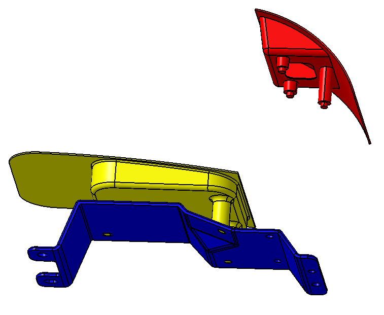
We will use the Pattern Rigid Move to remove the interference between the Turnlamp pins and the Bracket holes. The purpose of the Pattern Rigid Move is to assemble two rigid parts that use patterns of pins and holes as the secondary and tertiary locators. When Nominal Build is performed, the move routine will fit together the patterns of holes and pins. Since the Pattern Rigid Move is locating only the secondary and tertiary locators, a preliminary move is first needed to move the object part primary locators to the target part primary locators. This can be done with a preliminary move such as a Step Plane Move which we already have for the Turnlamp.
•Click the ![]() Moves button then select the Lamp_SubAsmLamp_SubAsm_Lesson8.
Moves button then select the Lamp_SubAsmLamp_SubAsm_Lesson8.
•Select Pattern Rigid from the drop-down list next to [Add].

•Click [Add]. This will open the Pattern Rigid Move dialog.
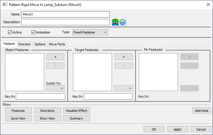
•Change the Name to "Turnlamp-to-Bracket_Pattern".
•Add the Description of "4way, 2way, and clearance hole and pin pattern.".
•Set the Type to Fixed-Fastener.
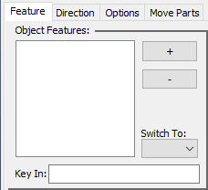
•Select the Feature tab.
•Under Object Features, select [ + ].
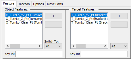
•Select the points O_TurnLp_YZ_Pt, O_TurnLp_Y_Pt, and O_TurnLp_Clear_Pt in the Turnlamp.
•Click [Close] to close the Select dialog.
•Under Target Features, select [ + ].
•Select the points T_TurnLp_YZ_Pt, T_TurnLp_Y_Pt, and T_TurnLp_Clear_Pt in the Bracket.
•Click [Close] to close the Select dialog.
The Feature tab should look like the following image. When this Move is executed 3DCS will attempt to line up each of the pin-hole pairs so it is important to make sure the object and target lists are in the same order, pairing up the corresponding features.
•Select the Direction tab.
•Set the Dir. Type to AssocDir.
•Select the Move Parts tab.
•Verify the Turnlamp is in the Move Parts list.
•Click [OK] to save the move and close the dialog.
•Click [OK] to close the Moves dialog.
Before running the analysis we will do a quick exercise to better understand how the Pattern Rigid Move is working with the Step Plane Move.
•Select ![]() Nominal Build and take note of the Turnlamp and Headlamp translating to the correct location on the Bracket.
Nominal Build and take note of the Turnlamp and Headlamp translating to the correct location on the Bracket.
•Click ![]() Separate.
Separate.
•Right-click on the Turnlamp-to-Bracket move in the tree and select Activate/Deactivate to turn off the Move.
•Select ![]() Nominal Build again and notice that the Turnlamp only slides over to meet the three holes in Bracket but does not translate at all to meet up with the faces of the Bracket.
Nominal Build again and notice that the Turnlamp only slides over to meet the three holes in Bracket but does not translate at all to meet up with the faces of the Bracket.
This is why the Step Plane Move is still an important part of our model. The Pattern Rigid Move has overwritten three DoF but the Turnlamp is still getting its primary location (first three DoF) from the Step-Plane Move.
•Right-click on the Turnlamp-to-Bracket move and select Activate/Deactivate again to turn the move back on.
•Select ![]() Nominal Build then
Nominal Build then ![]() Run Analysis.
Run Analysis.
•Leave Recommendation based on convergence on STD enabled.
It is possible that the Pattern Rigid Move cannot find a solution for a specific build (pins too close together/too big, holes too far apart/too small, etc.). If 3DCS comes across a build where, for whatever reason, the Turnlamp cannot be assembled to the three holes of the Bracket then it determines that build is a failed build. From here, we can decide whether we want to keep these failed builds in our statistics or not. In this case we are specifically checking interference that the Pattern Rigid Move would deem a failed build (any time there is interference between a pin and a hole 3DCS will return a failed build), so we want to keep the failed builds in our statistics. If, for example, we were only checking the gap between the Turnlamp and the Headlamp still then it is possible that we would not want to contaminate our results by including builds where the Turnlamp could never physically build to the Bracket. That is not the case for the results we are checking on the measures we just made so we will turn this option on.
•In the Options tab of the Run Analysis dialog, check the box for Calculate statistics for No Builds.
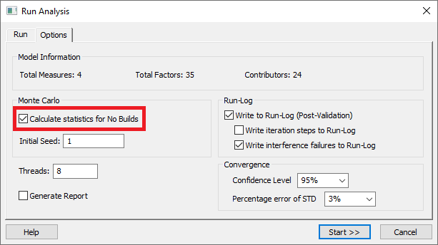
•Click [Start>>].
Notice the Run Log Viewer window that now appears after the Simulation runs. It lists all of the runs that failed to build with the Pattern Rigid Move. It also tells what the user can change to make the pins and holes fit for each build. At the bottom of the Run Log Viewer window, the largest hole diameter increment needed to solve all builds is listed.
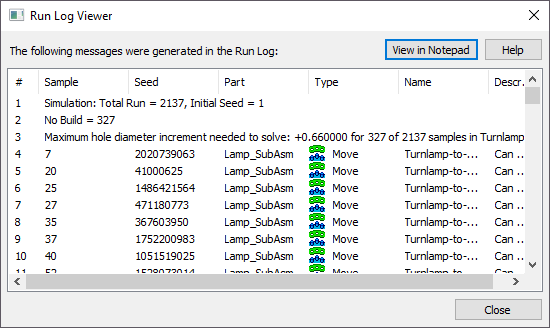
>>> Your results may not match the above illustration <<<
Go to the TurnLp_Clearance-HP measure and notice the difference in the results from before the Pattern Rigid Move. Now, far fewer runs are falling below the lower spec limit than they did without the Pattern Rigid Move.
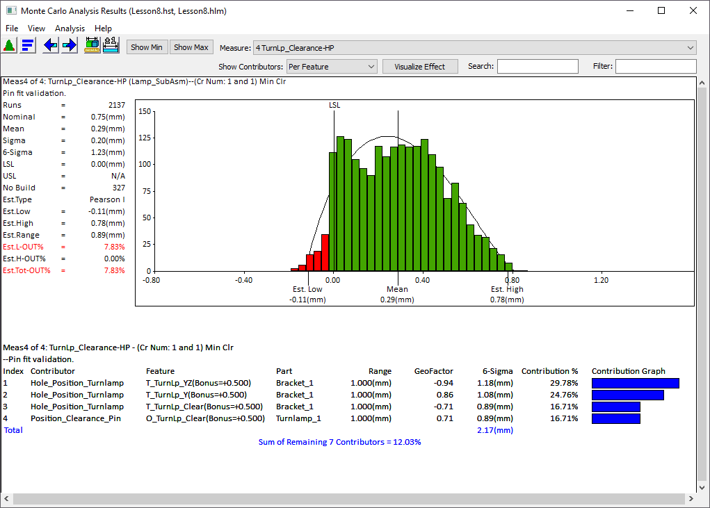
>>> Your results may not match the above illustration <<<
Notice that there is now a new statistic in the statistics section to the left of the distribution called No Build. This statistic notes how many of the 2000 Runs in this model that the Pattern Rigid Move could not build. To resolve the issue with no builds, we would have to adjust our hole or pin sizes for more clearance or tighten the position tolerances. Be careful as adding more clearance by increasing the nominal hole diameter or decreasing the nominal pin diameter to ensure the parts always fit together could increase the variation of the gap. Tightening tolerances could make the parts more expensive to produce, so there are trade-offs for both approaches. These are scenarios that can be tested using 3DCS but will be left to you to try on your own.
•Click ![]() Separate.
Separate.
•Save the model.