Next, we will look at several functions of the Graphical Analysis toolbar. This toolbar contains the functions for visualizing the assembly process and deviations of the model. The Graphical Analysis toolbar contains the following icons:
Verify the mesh is displayed on the parts. The global display of the mesh is controlled by ![]() Show Mesh. If the icon is blueactivated, the global display of the mesh is on. If the icon is greydeactivated, the global display of the mesh is off.
Show Mesh. If the icon is blueactivated, the global display of the mesh is on. If the icon is greydeactivated, the global display of the mesh is off.
•If the mesh is off, click on ![]() Show Mesh to turn the mesh on.
Show Mesh to turn the mesh on.
•Click on the ![]() Deviate button to show the variation of the tolerances.
Deviate button to show the variation of the tolerances.
The surfaces with Tolerances on the Bracket, Headlamp, and Turnlamp will start deviating. This represents the variation from part to part according to the active Tolerances. If the surface mesh is deviating too fast, increase the Delay to slow it down. You can also ![]() Pause and
Pause and ![]() Play
Play![]() Pause and
Pause and ![]() Play
Play ![]() Pause and
Pause and ![]() Play the deviations.
Play the deviations.
•Click [Close] in the Deviate dialog to stop the deviation.
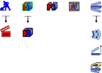
•Click ![]() Nominal Build.
Nominal Build.
![]() Nominal Build applies all active Moves in the model to locate parts in their built position using nominal part geometry. Notice that the
Nominal Build applies all active Moves in the model to locate parts in their built position using nominal part geometry. Notice that the ![]() Creation Mode icon changes to the
Creation Mode icon changes to the ![]() Animation Mode icon automatically after selecting
Animation Mode icon automatically after selecting ![]() Nominal Build.
Nominal Build. ![]() Creation Mode is used when creating or modifying Moves, Tolerances, Measures in the model.
Creation Mode is used when creating or modifying Moves, Tolerances, Measures in the model. ![]() Animation Mode is used to visualize the build process or variation in the model.
Animation Mode is used to visualize the build process or variation in the model.
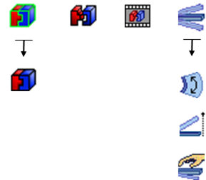
•Click ![]() Deviate.
Deviate.
With the parts in the built position, ![]() Deviate will show how the variation of the parts stack up through the Moves to affect the final position of the parts. Each run is a new combination of parts with unique geometry due to variation from the Tolerances.
Deviate will show how the variation of the parts stack up through the Moves to affect the final position of the parts. Each run is a new combination of parts with unique geometry due to variation from the Tolerances.
•Click [Close] in the Deviate dialog.
•Click ![]() Separate to return the parts to their position before the Moves were applied. In 3DCS, you must
Separate to return the parts to their position before the Moves were applied. In 3DCS, you must ![]() Separate before you can save.
Separate before you can save.
•Click ![]() Animate. This opens the Animate dialog.
Animate. This opens the Animate dialog.
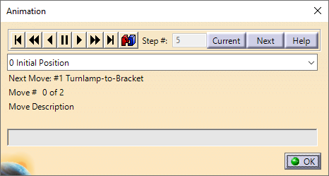
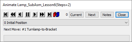
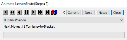
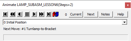
![]() Animate is used to show the build process step-by-step.
Animate is used to show the build process step-by-step.
•Click on ![]() Forward One Assembly to animate the first Move.
Forward One Assembly to animate the first Move.
•Click on ![]() Forward One Assembly again to animate the second Move.
Forward One Assembly again to animate the second Move.
•Click [OK][Close] to close the Animation dialog.
•Click the ![]() Animation Mode button to return to
Animation Mode button to return to ![]() Creation Mode. The parts will return to their position set by 3DEXPERIENCECATIA V5.
Creation Mode. The parts will return to their position set by 3DEXPERIENCECATIA V5.